

HELM Damper Complete 100 Hour Service Instructions (Part 2 of 3)
June 2022 orig.
Table of Contents
Recommendations and Warnings
Cane Creek recommends only trained suspension technicians perform service on all suspension, using all required tools and following all proper procedures. Anyone without access to the proper equipment or with any concerns on the procedures should defer to an authorized Cane Creek service center for service. Improper service can result in loss of performance or suspension failure. All Cane Creek forks have pressurized oil. Follow the service procedures exactly as written to avoid possible injury or harm to the suspension. Always wear eye protection while performing suspension service. Please dispose of all waste products and materials through proper channels to avoid contamination of the environment.
Any damage or issues resulting from improper service will not be covered by warranty. If you have a fork still in its original warranty period and do not wish to void your warranty, please contact an authorized Cane Creek service center.
These service instructions cover the basic service procedures using standard service kits. If your suspension requires parts beyond standard replacement parts – CSU, compression rods, etc. – please consult your authorized Cane Creek service center or contact us at our Cane Creek Support Center.
Service Notes
These instructions cover just the damper leg of a complete 100 hour service. Combine these instructions with the appropriate spring side – air or coil; original or MKII – and 50 hour lower service to get a complete 100 hour fork service.
Additionally, follow these instructions for damper removal and reinstall if sending the damper off for a service with an authorized Cane Creek service center.
Service Kit
BAG0714 – HELM Damper Rebuilt Kit
Required Cane Creek Tools
BAG0405 – Compression Retaining Nut Socket – Thin Walled 11mm socket
AAG0086 – HELM Cartridge Fill Tool
AAG0367 – HELM Oil Seal Head Bullet
AAG0406 – HELM Compression Outer Sleeve Spanner
Additional Tools & Supplies
Allen wrenches – 4mm
Torx wrenches – T10
Sockets – 10mm & chamfer-less 30mm
Crowfoot wrenches – 10 & 18mm
Open Ended Box wrenches – 10 & 18mm
10mm Shaft Clamp
Torque wrenches
Knipex pliers
Pick
Suspension Grease
PolyLube Grease
Motorex 2.5wt Racing Fork Oil
Vacuum Oil Fill Machine
Torque, Loctite, Oil & Nitrogen Specs
Torque & Loctite Chart
| Part | Torque Spec | Loctite Spec |
|---|---|---|
| Rebound Piston Assembly | 3 Nm | 263 (Red) |
| Rebound Piston Install | 5 Nm | 243 (Blue) |
| Rebound Adjuster | 5 Nm | 243 (Blue) |
| Damper Top Cap to Gold Coupling | 9 Nm | None |
| Oil Seal Head to Damper Tube | 13 Nm | None |
| Damper Install | 36 Nm | 243 (Blue) |
| Compression Nut | Hand Tight | 243 (Blue) |
| LSC Knob Screw | 1.6 Nm | 243 (Blue) |
Oil Chart
| Oil Location | Oil Type | Oil Amount |
|---|---|---|
| Damper Fill | Motorex 2.5wt Racing Fork Oil | Fill to 2 Bars |
Damper Reassembly

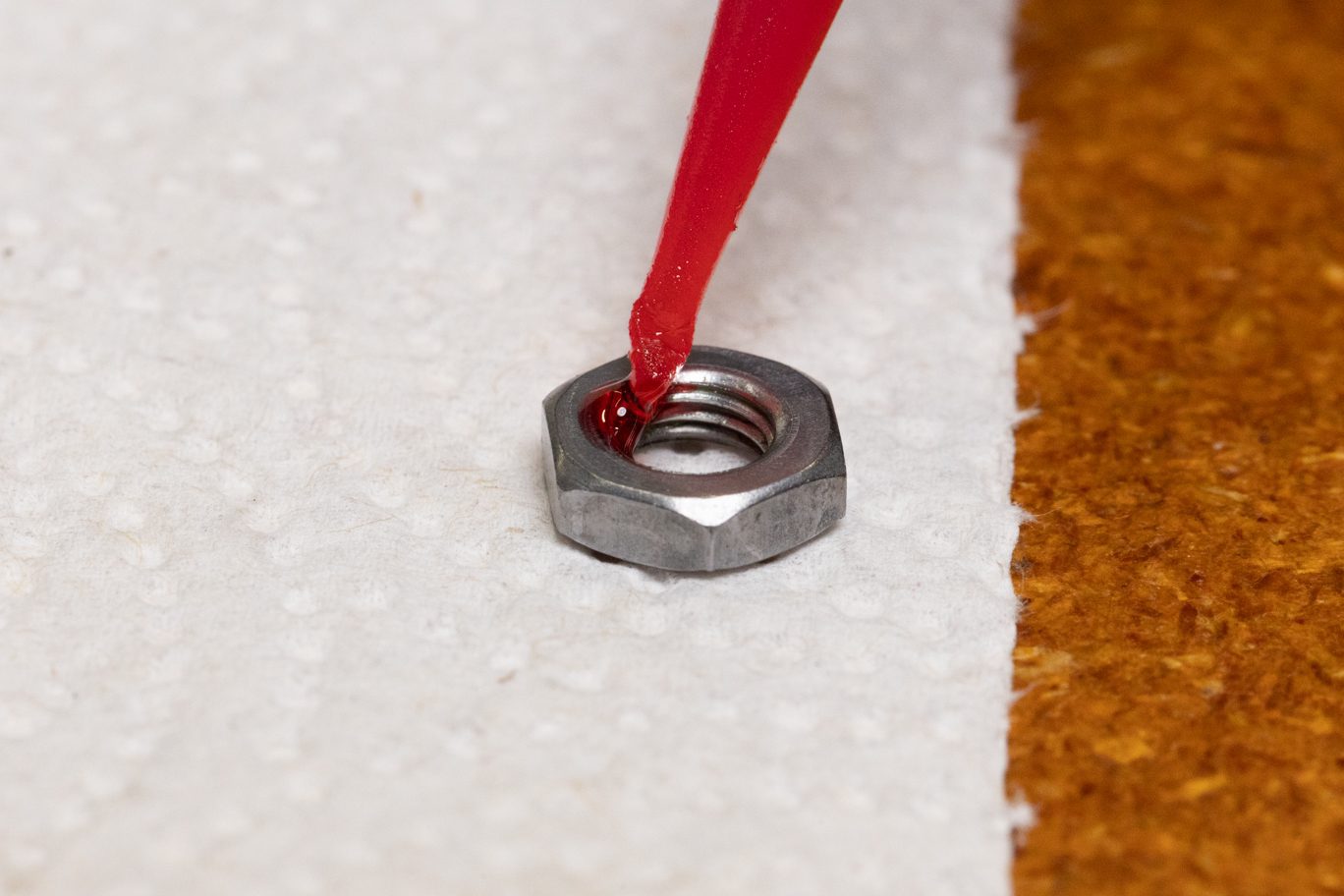
Step 1 – Rebound Piston Assembly (if necessary)
If necessary, install check spring or wave washer on piston seat with concave side up, bottom shim, piston with small ports facing up, shim stack, and spacer. Shim stack goes in order from largest to smallest. Apply red (263) Loctite to jam nut and install. Check that bottom shim is not pinched on piston seat and is centered. Using two 10mm sockets, torque to 3 Nm.
TSB015 – Rebound Piston Flip
TBS029 – Check Spring Change
Wave Washer (or Check Spring) on Piston Seat
Bottom Shim on Piston Seat
Wave Washer (or Check Spring) & Bottom Shim on Piston Seat
Rebound Piston Install
Rebound Piston Installed
Shim Stack Installed
Spacer Install
Spacer Installed
Applying Loctite to Jam Nut
Rebound Piston Assembly Ready for Torque
Rebound Piston Assembly w/ Check Spring
Rebound Piston Assembly on 10mm Socket
Rebound Piston Assembly Torque
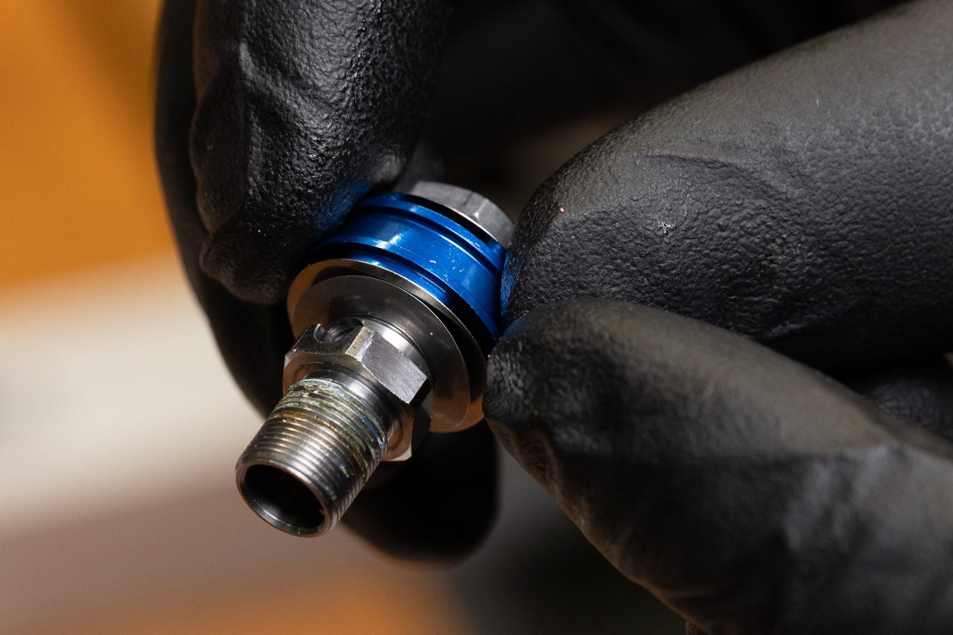
Step 2 – Rebound Piston Install (if necessary)
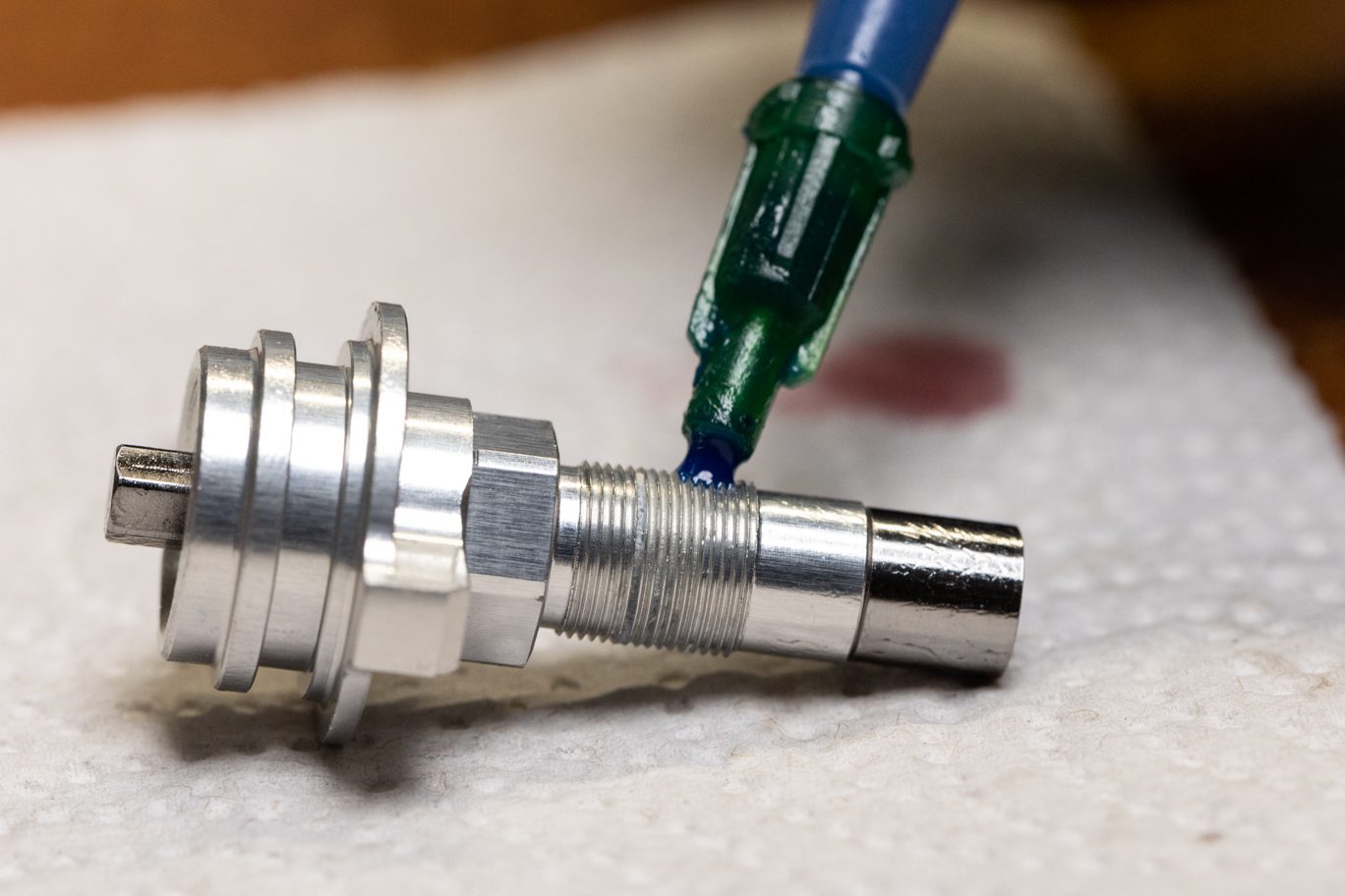
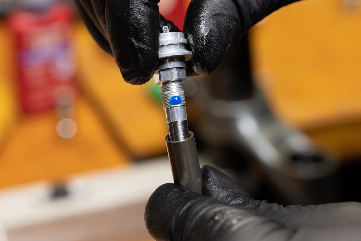
Install new piston band (AAG0212) on rebound piston. Apply blue Loctite (243) to rebound piston assembly threads and install into damper shaft. Reinstall low speed needle spring if removed. Clamp damper shaft with 10mm shaft clamp with piston end up. Torque piston assembly to 5.0 Nm with 10mm crowfoot.
Piston Band Install
Applying Loctite to Piston Assembly
Low Spring Needle Spring Install
Piston Assembly Install
Piston Assembly Torque

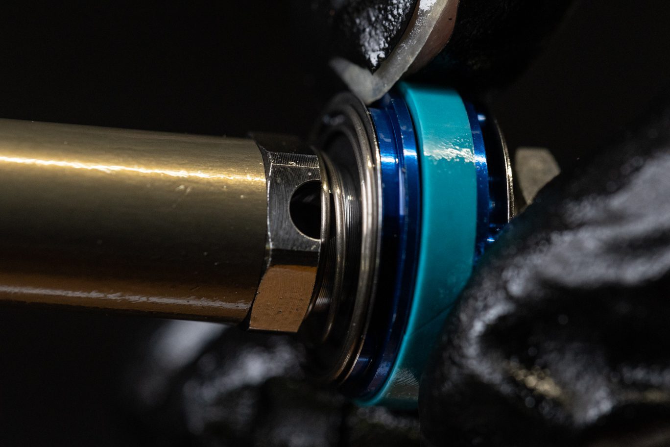
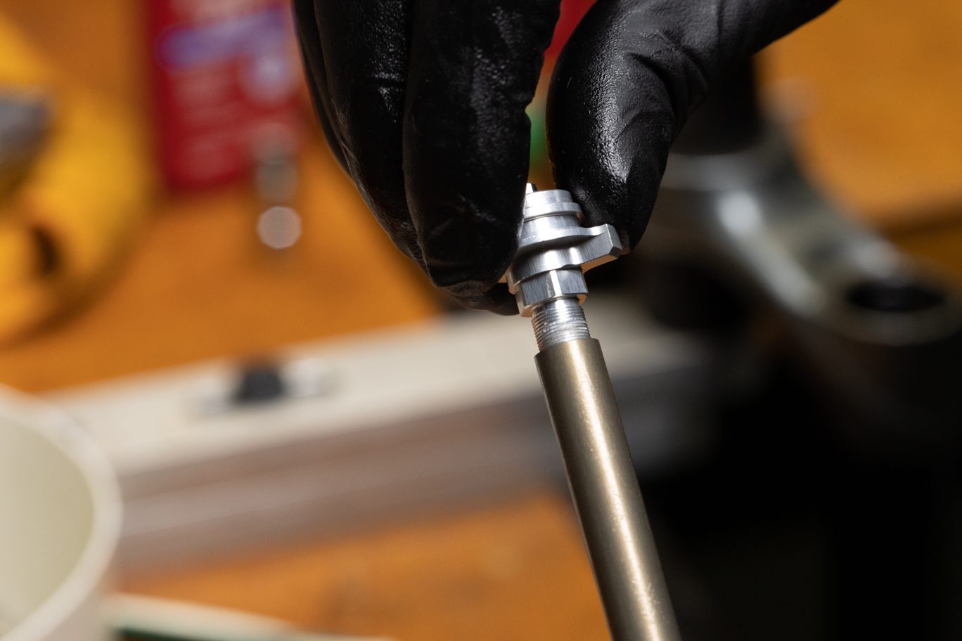
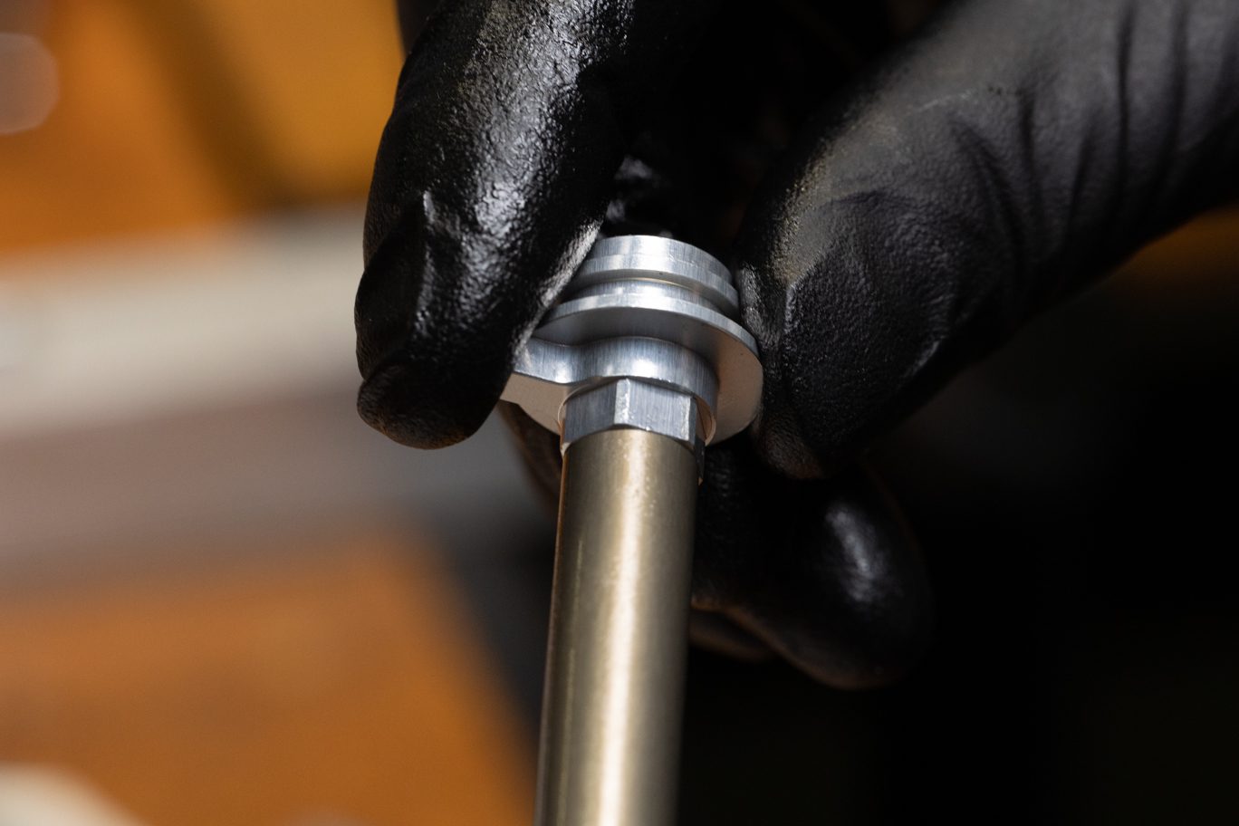
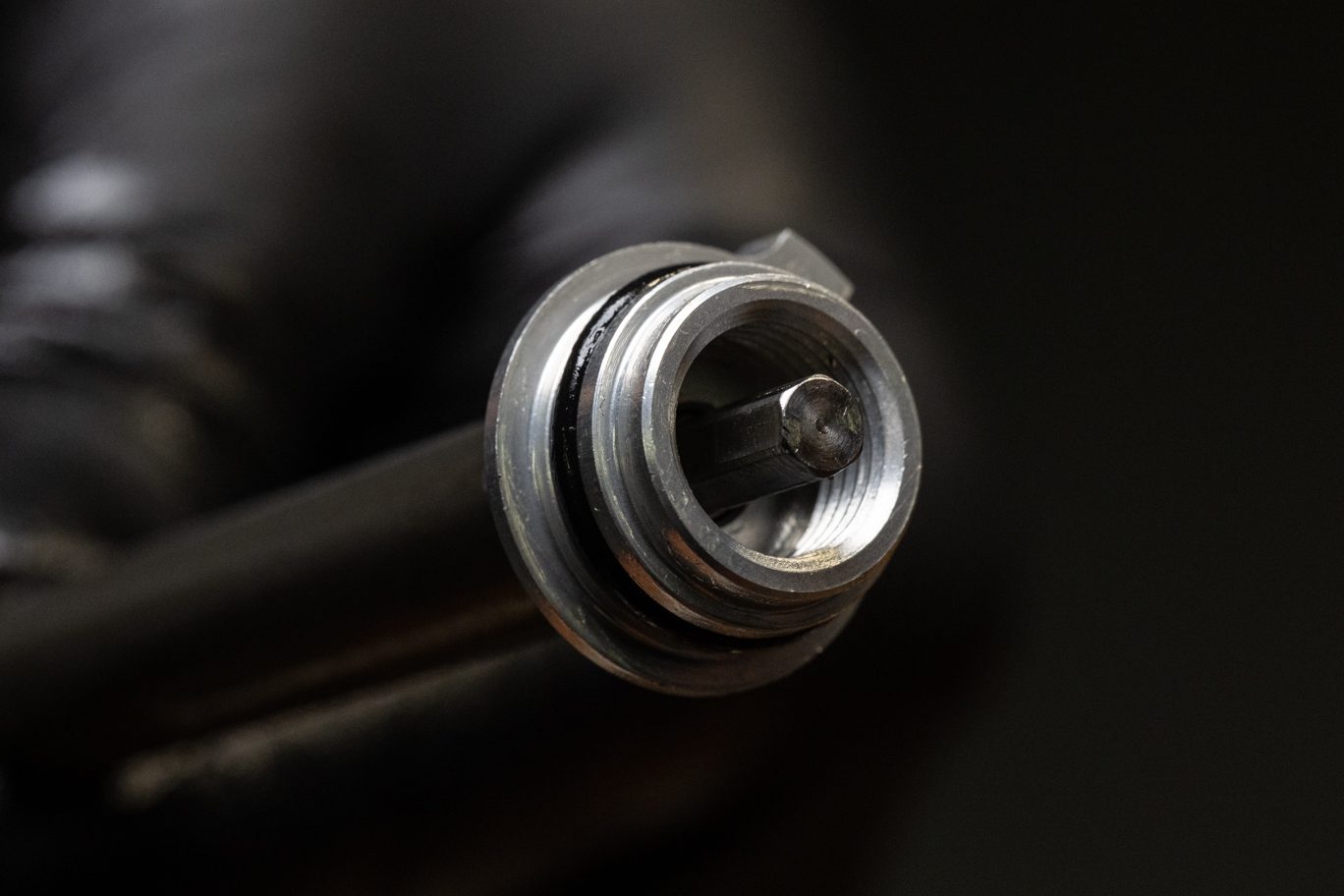
Step 3 – Oil Seal Head Install
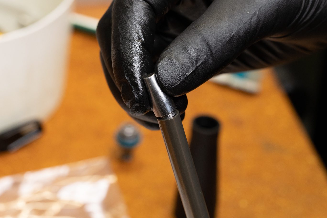
Grease bushing on new oil seal head (AAG0208). Using Oil Seal Head bullet (AAG0367), install oil seal head onto damper shaft. Note orientation with threaded side towards piston end of shaft.
Greasing Oil Seal Head
Oil Seal Head Bullet
Oil Seal Head Install
Oil Seal Head Installed
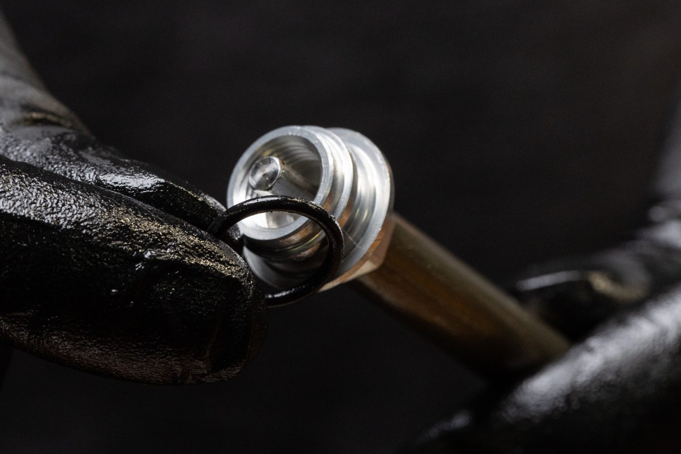
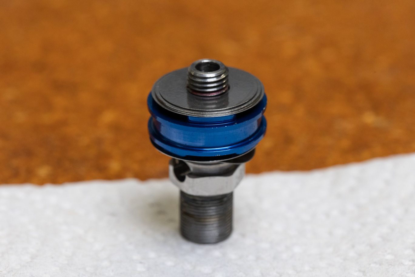
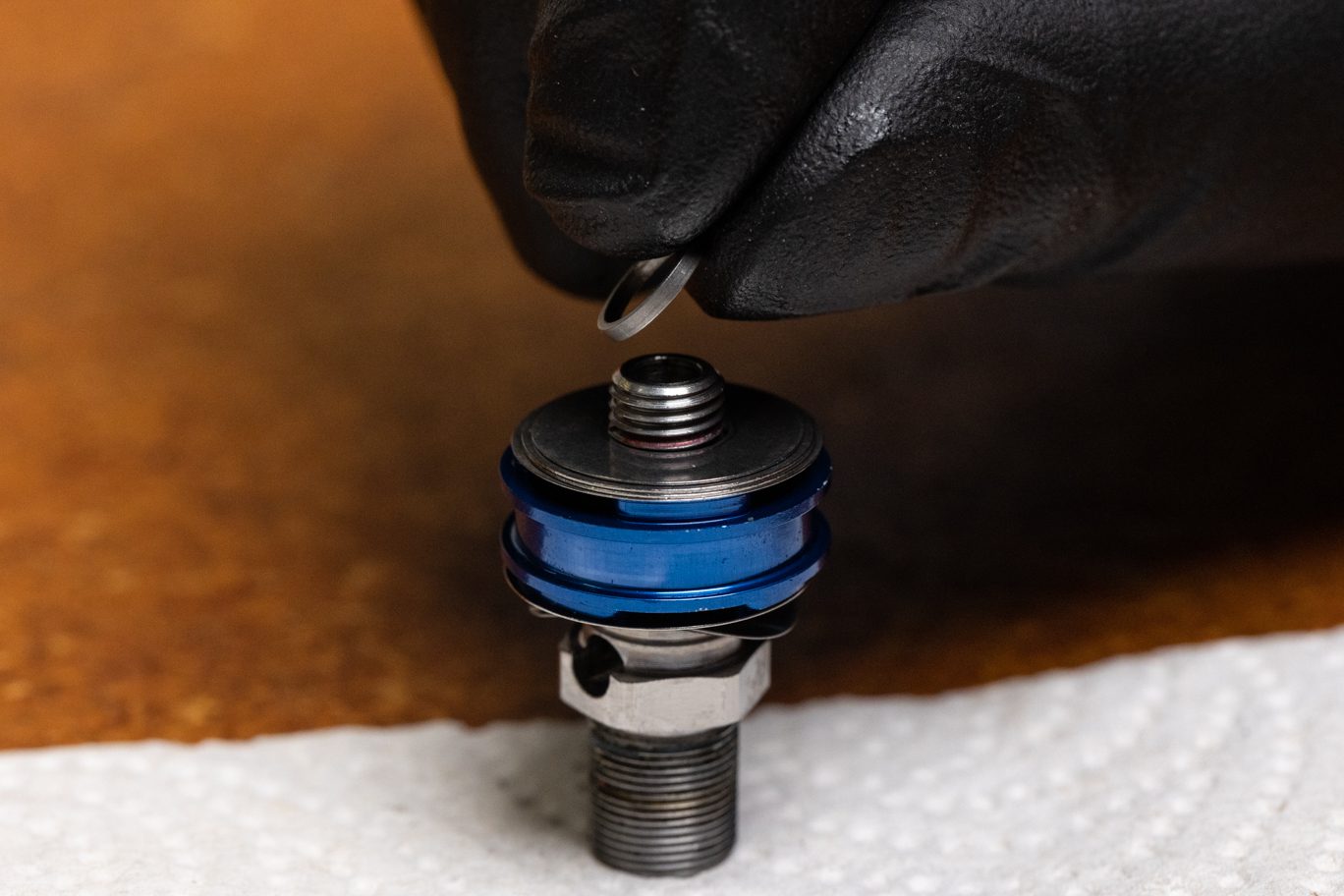
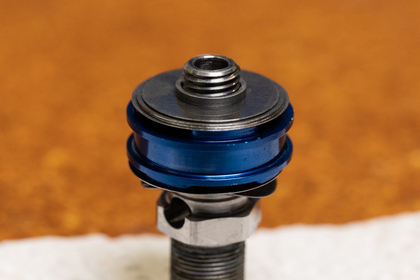
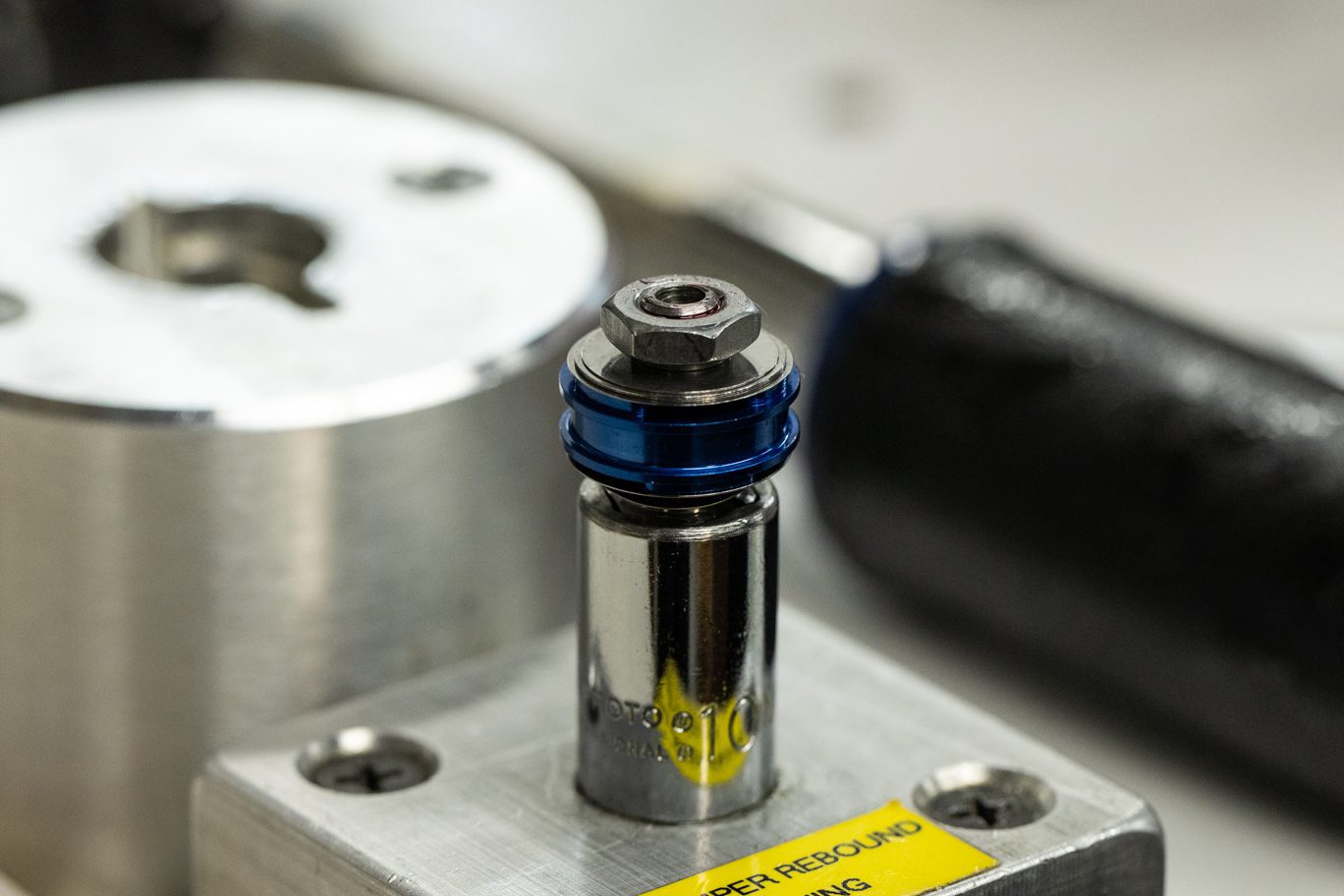
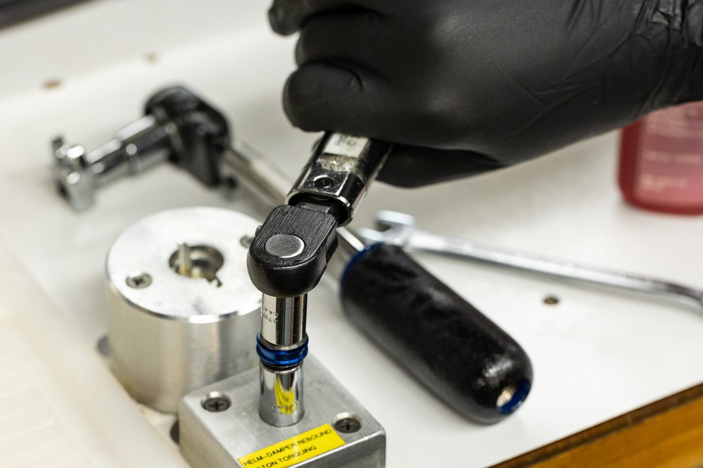
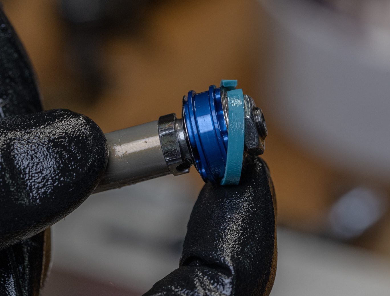
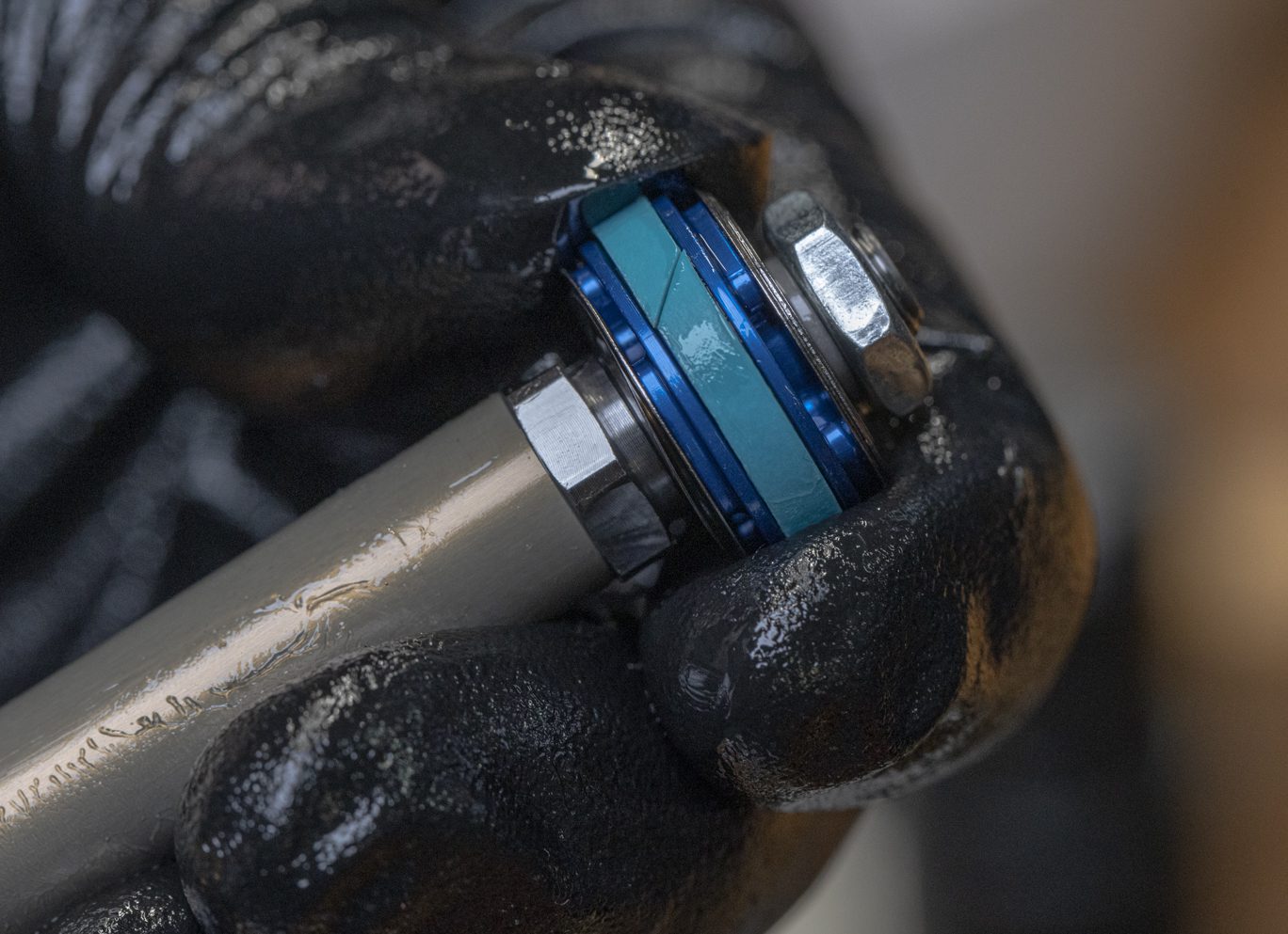
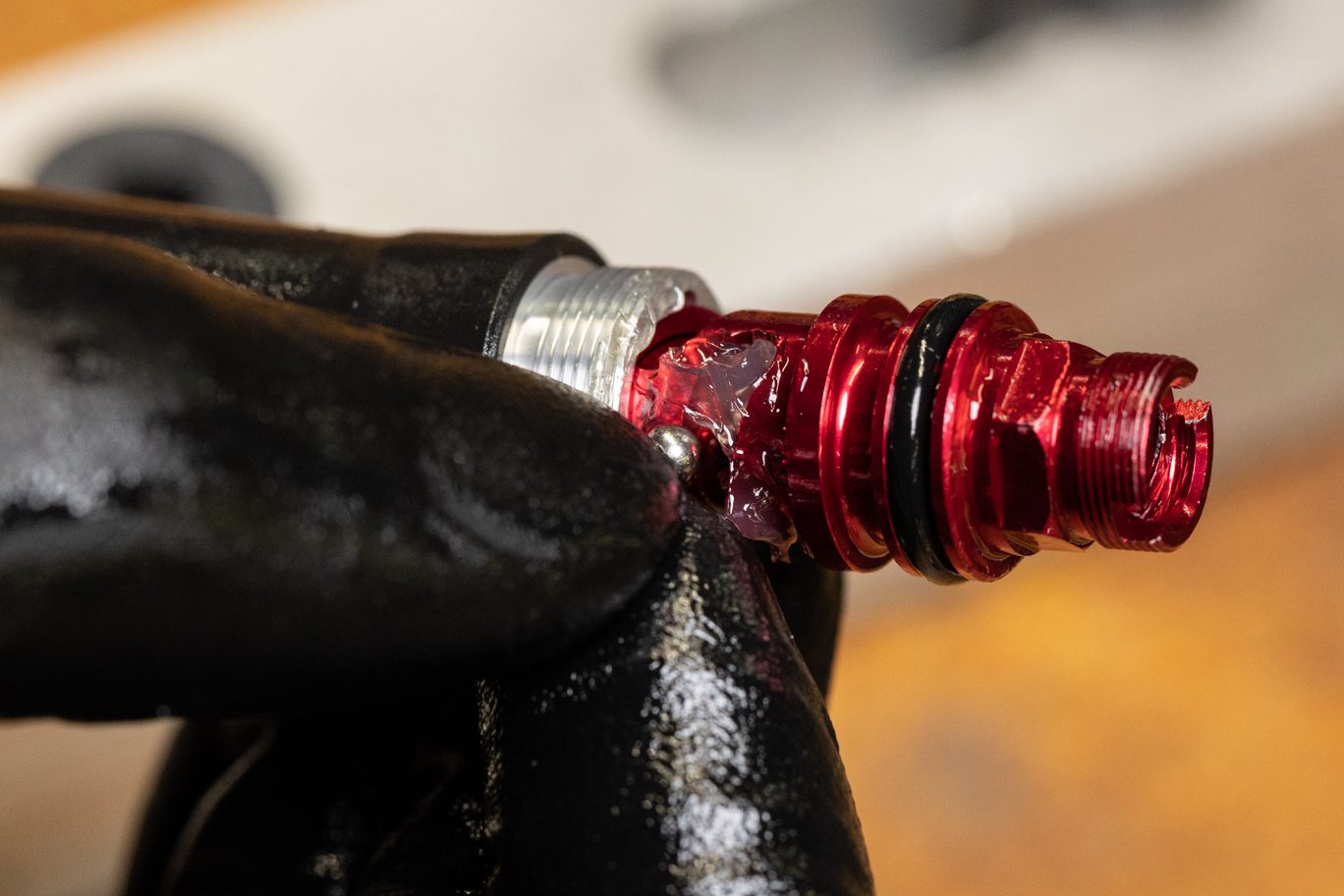
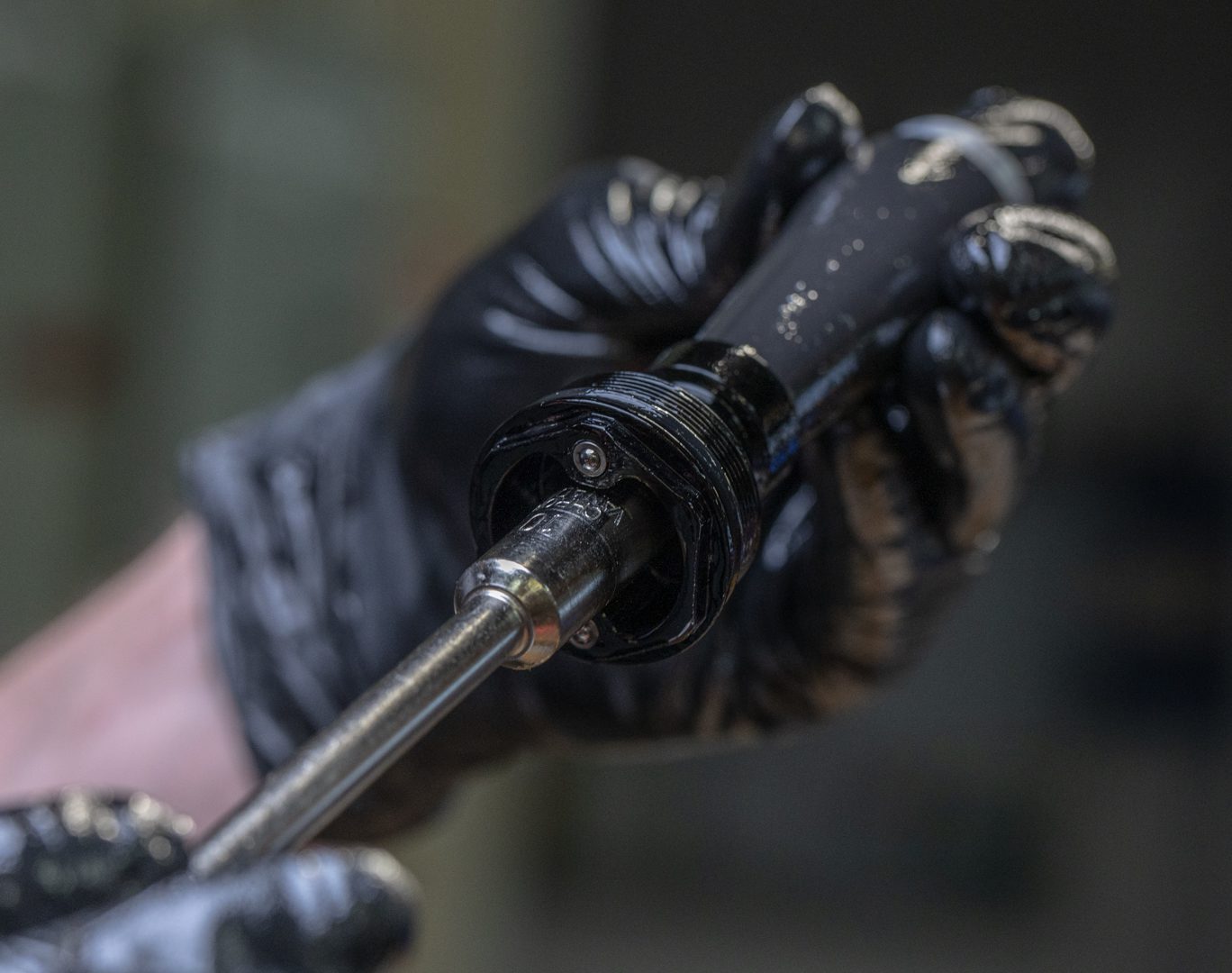
Step 4 – Rebound Adjuster Install
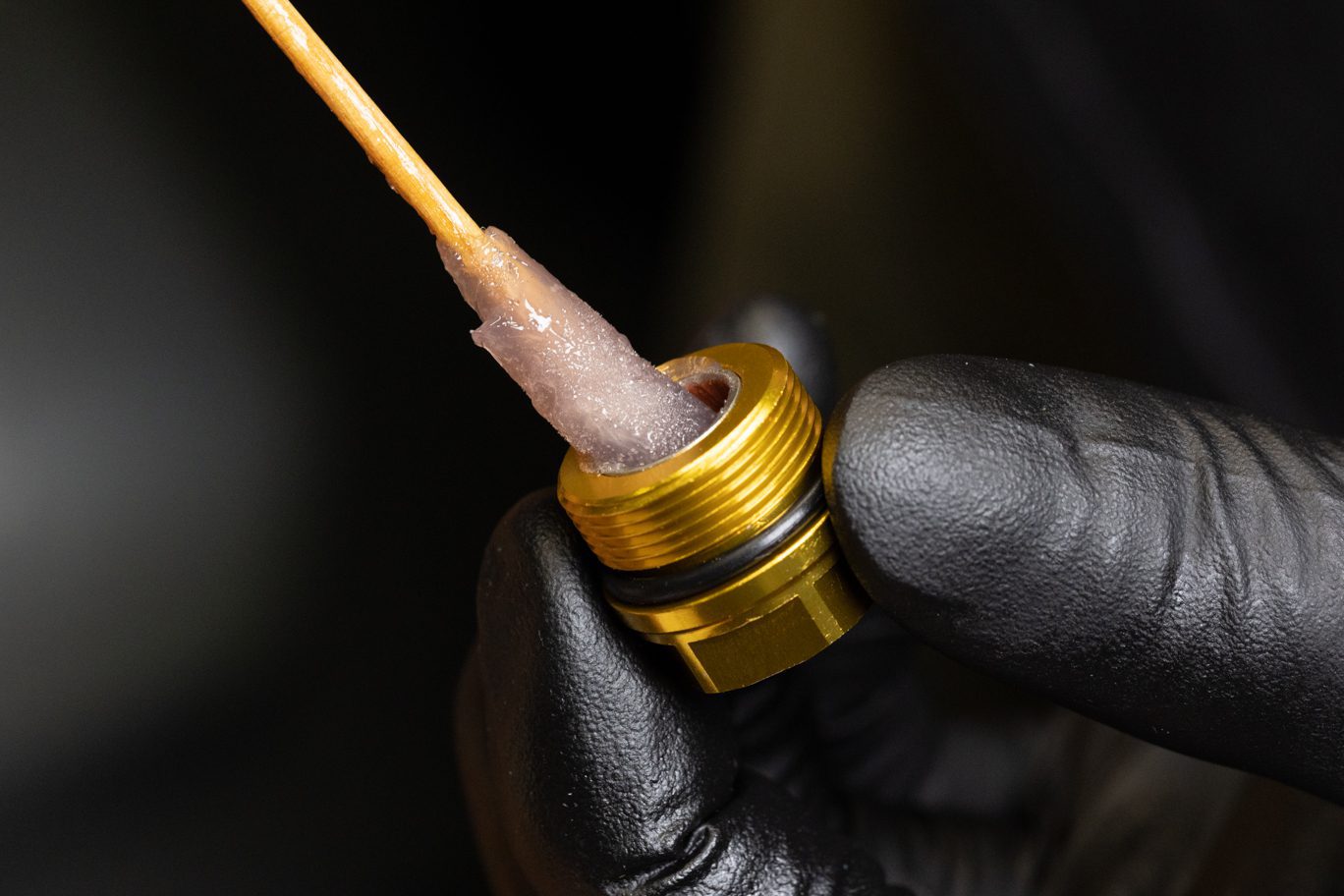
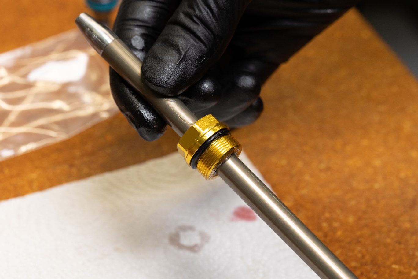
Insert rebound shuttle rod into damper shaft. Apply blue Loctite (243) to rebound adjuster threads. Install rebound adjuster into damper shaft. Clamp damper shaft with 10mm shaft clamp. Torque adjuster to 5.0 Nm with 10mm crowsfoot. Grease and install rebound adjuster o-ring (AAD1060).
Rebound Shuttle Rod Install
Applying Loctite to Rebound Adjuster
Rebound Adjuster Install 1
Rebound Adjuster Install 2
Rebound Adjuster Installed
Shaft Clamped for Rebound Adjuster Torque
Rebound Adjuster Torque
Rebound Adjuster O-Ring Install
Rebound Adjuster O-Ring Installed
Step 5 – Piston Band Install (if Step 2 skipped)
Install new piston band (AAG0212) on rebound piston.
Piston Band Install
Piston Band Installed
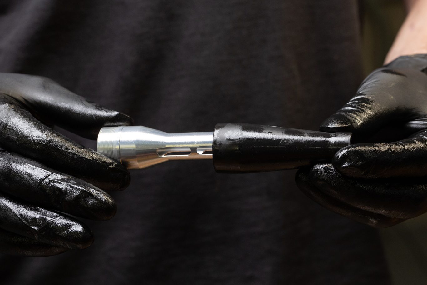

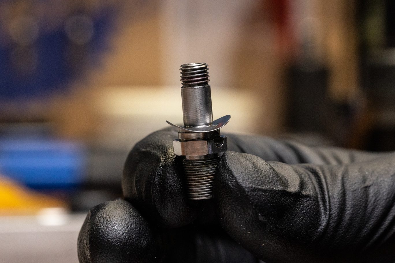
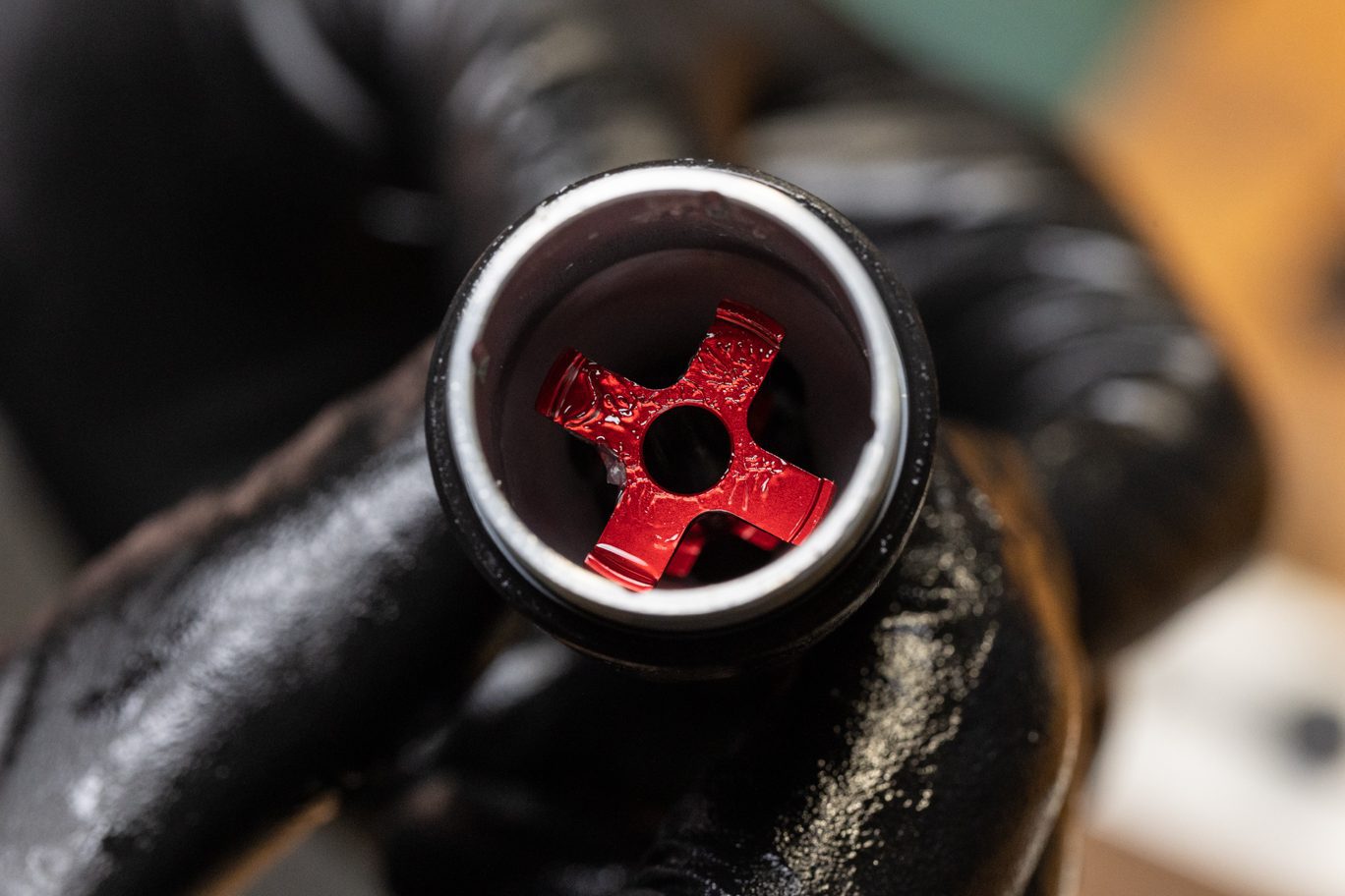
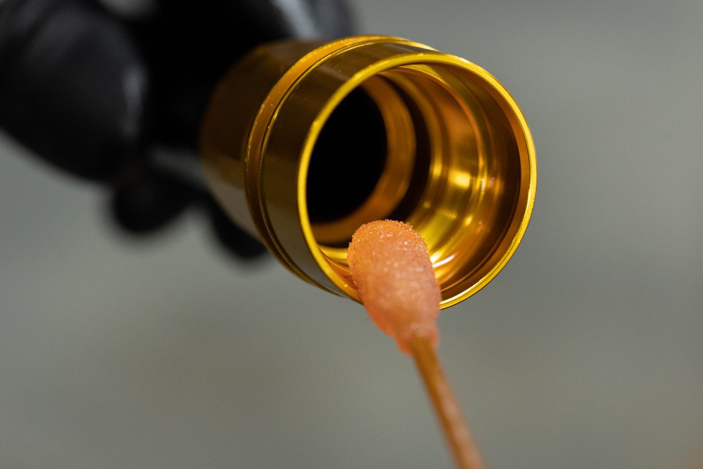
Step 6 – Bladder, Claw & Helix Install
Install new bladder (AAG0216HNBR) on compression outer sleeve. Ensure bladder and outer compression sleeve threads are exposed. Insert claw into compression outer sleeve. Holding claw in place, place helix onto claw.
Bladder Install
Bladder Installed
Ensuring Thread Exposure
Claw Install
Claw Install
Holding Claw for Helix Install
Holding Claw for Helix Install

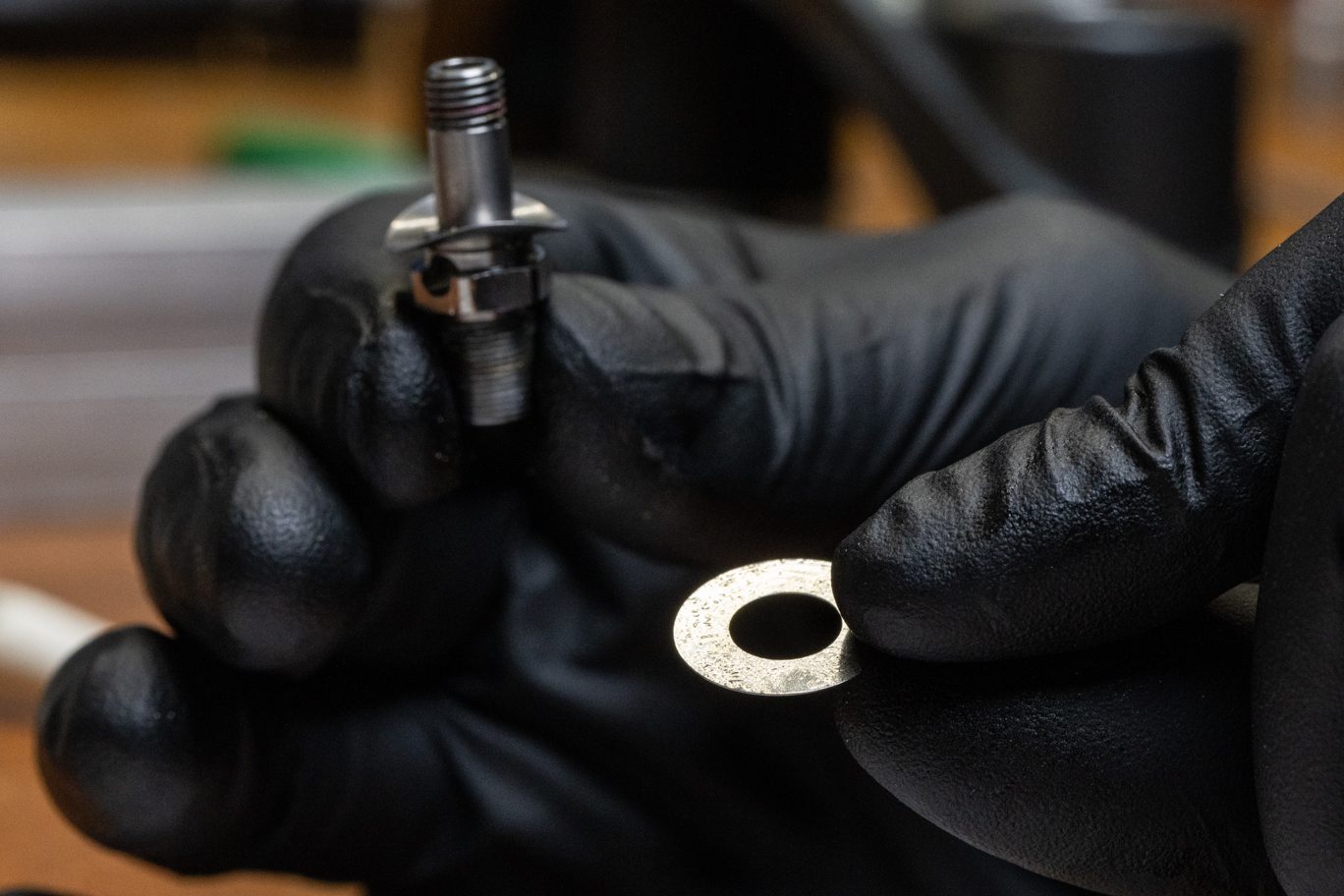
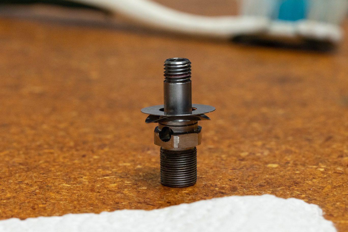
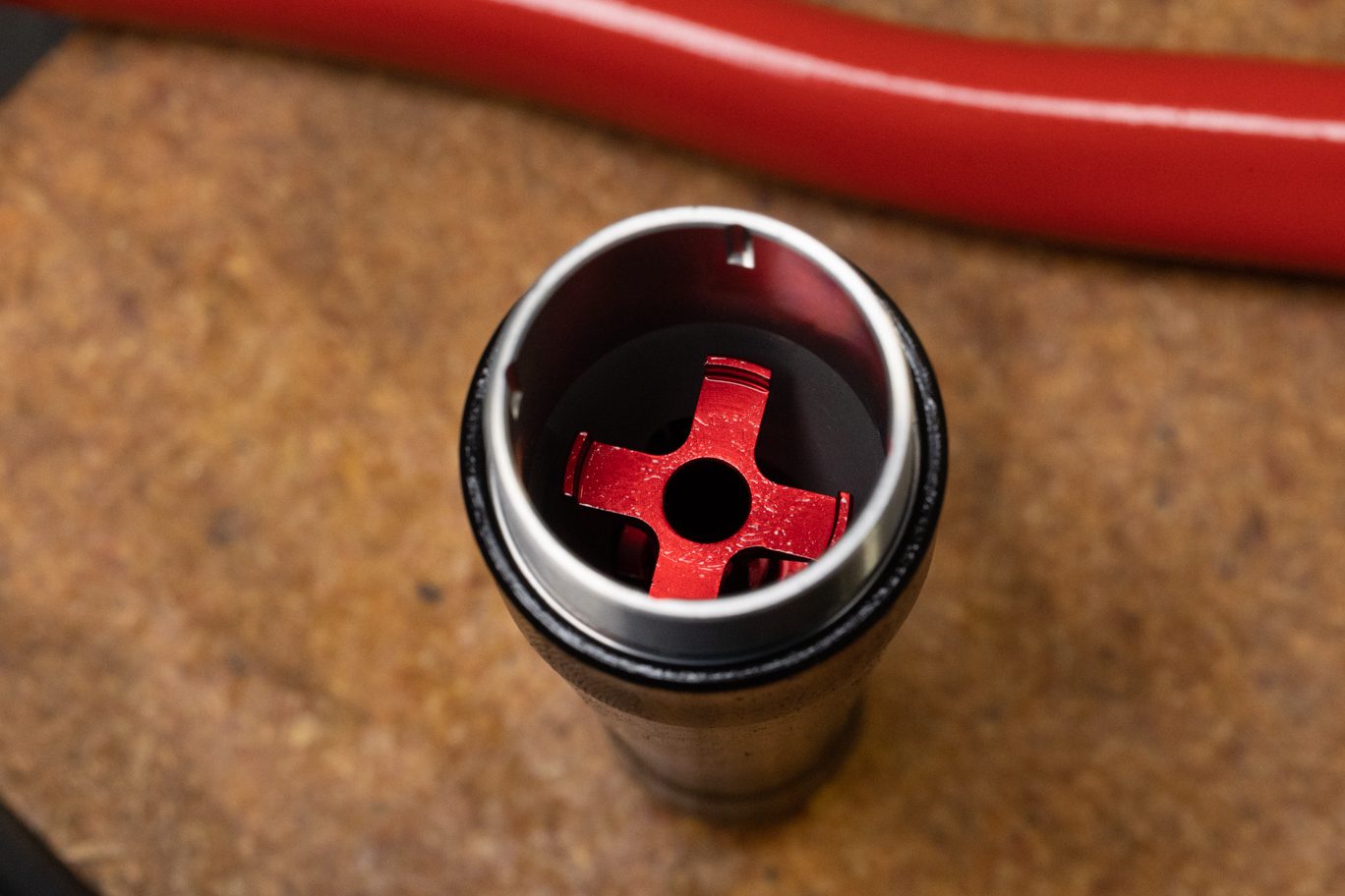
Step 7 – Detent Install
Apply suspension grease through the helix into the detent channel on the claw. Set the detent balls into the channel. Line up detent balls with channels on the outer sleeve and slide the helix & claw assembly into outer sleeve. Ensure claw moves up and down when rotating helix.
Detent Channels on Outer Sleeve
Applying Grease Through Helix
Detent Ball Install
Detent Ball Installed
Detent Balls Misaligned
Detent Balls Correctly Aligned

Step 8 – Damper Top Cap Install
Apply damper oil to inside of damper top cap. Holding claw in place, fully thread damper top cap onto compression outer sleeve. Using 10mm socket, check for free rotation of helix and claw. Leave fully open (counterclockwise).
Lubing Damper Top Cap
Holding Claw for Top Cap Install
Top Cap Install
Threading Damper Top Cap
Damper Top Cap Installed
Testing Helix & Claw 1
Testing Helix & Claw 2
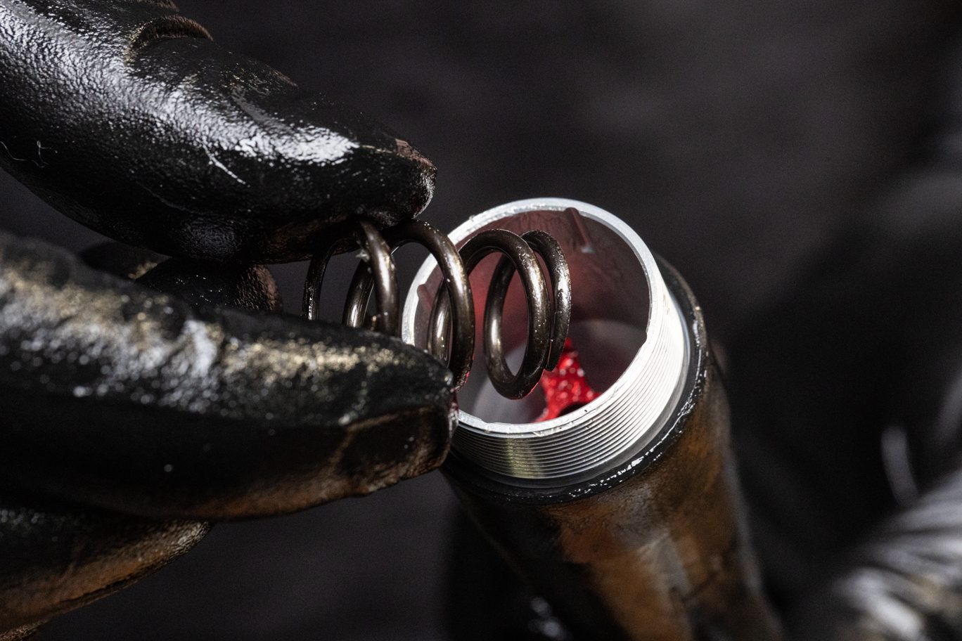
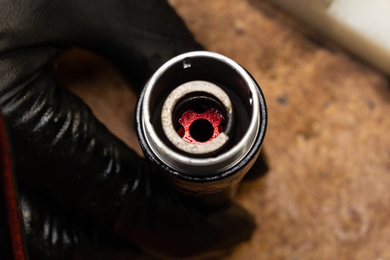
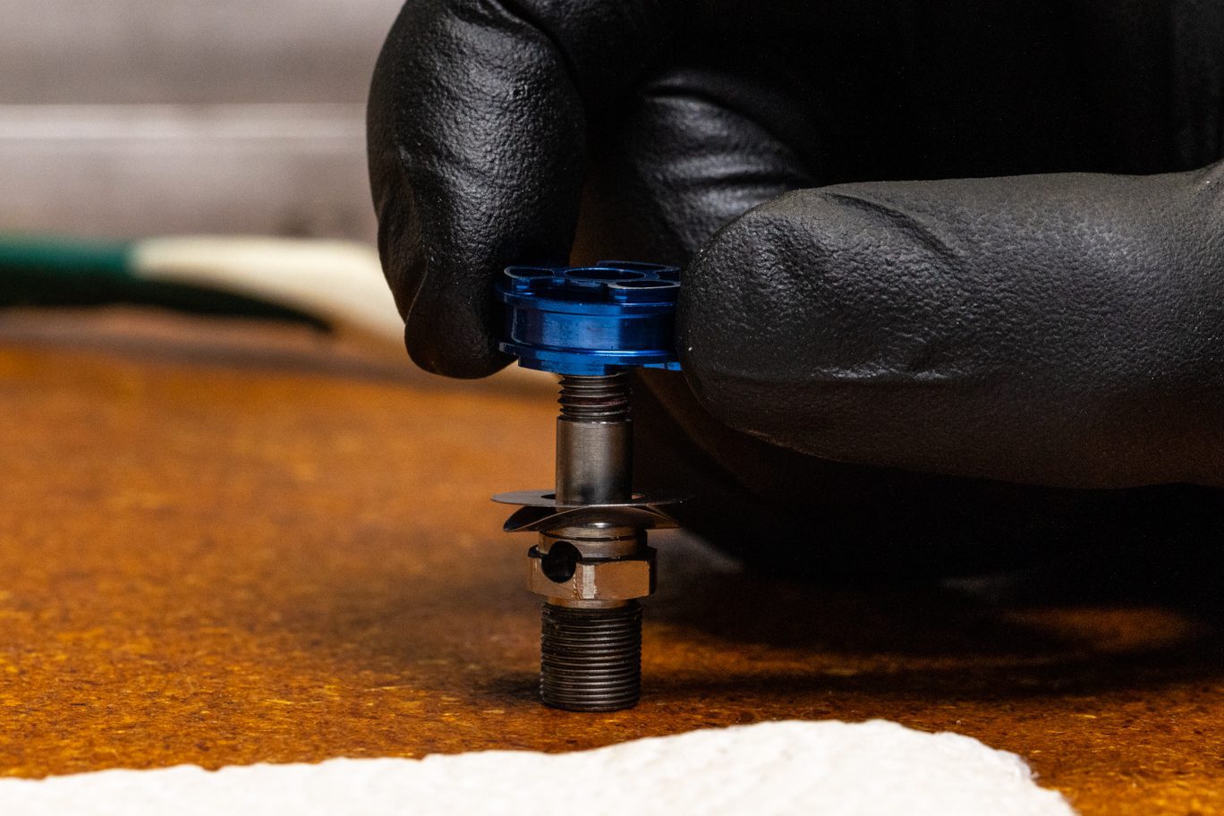
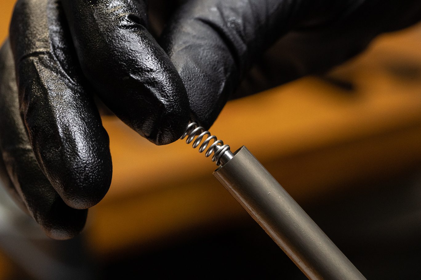
Step 9 – Check Spring & Piston Assembly Install
Install compression check spring onto claw. Install compression piston assembly with poppet contacting spring.
Compression Check Ring Install
Compression Check Ring Installed
Compression Piston Assembly Install
Compression Piston Assembly Installed

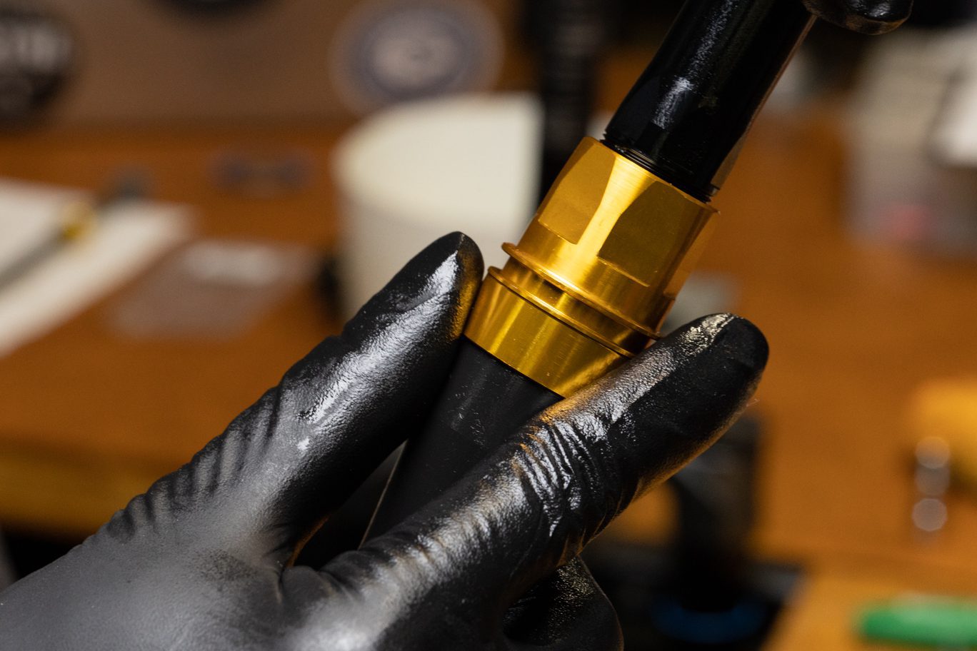
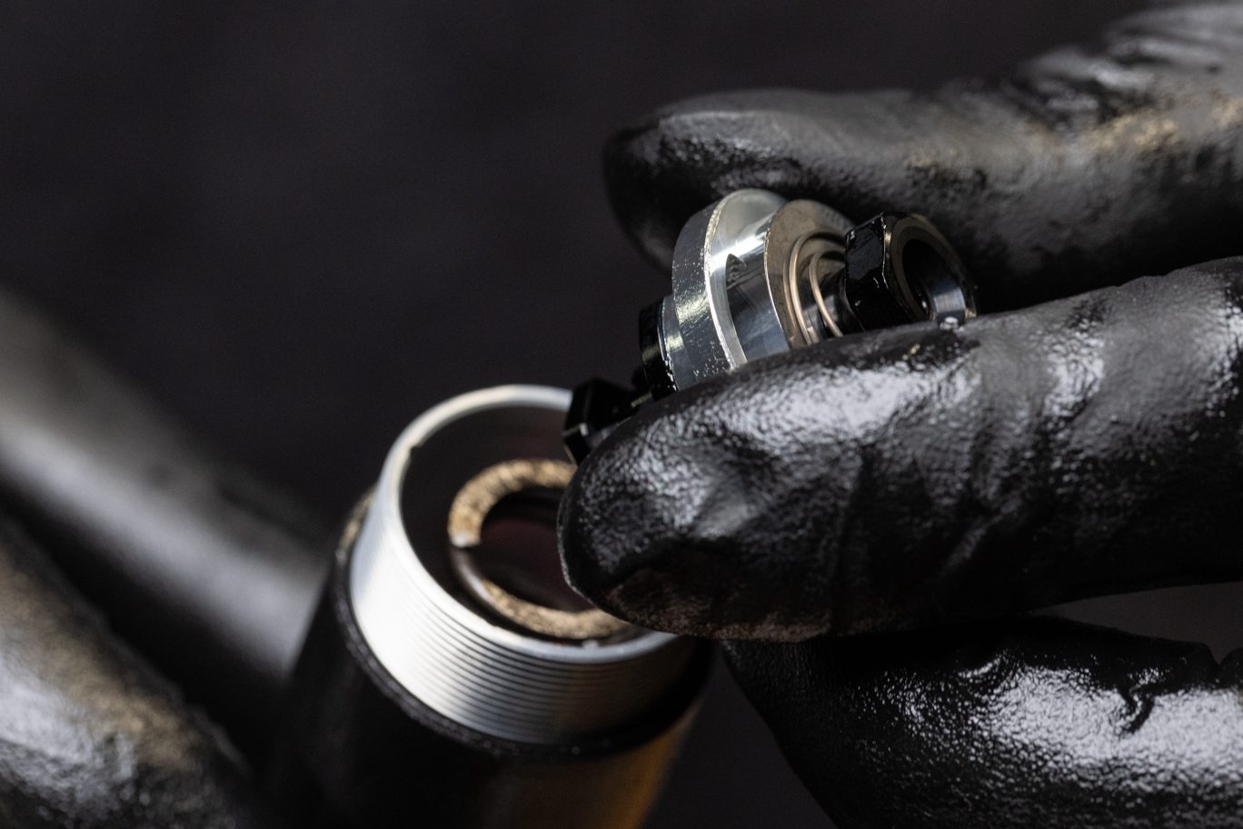
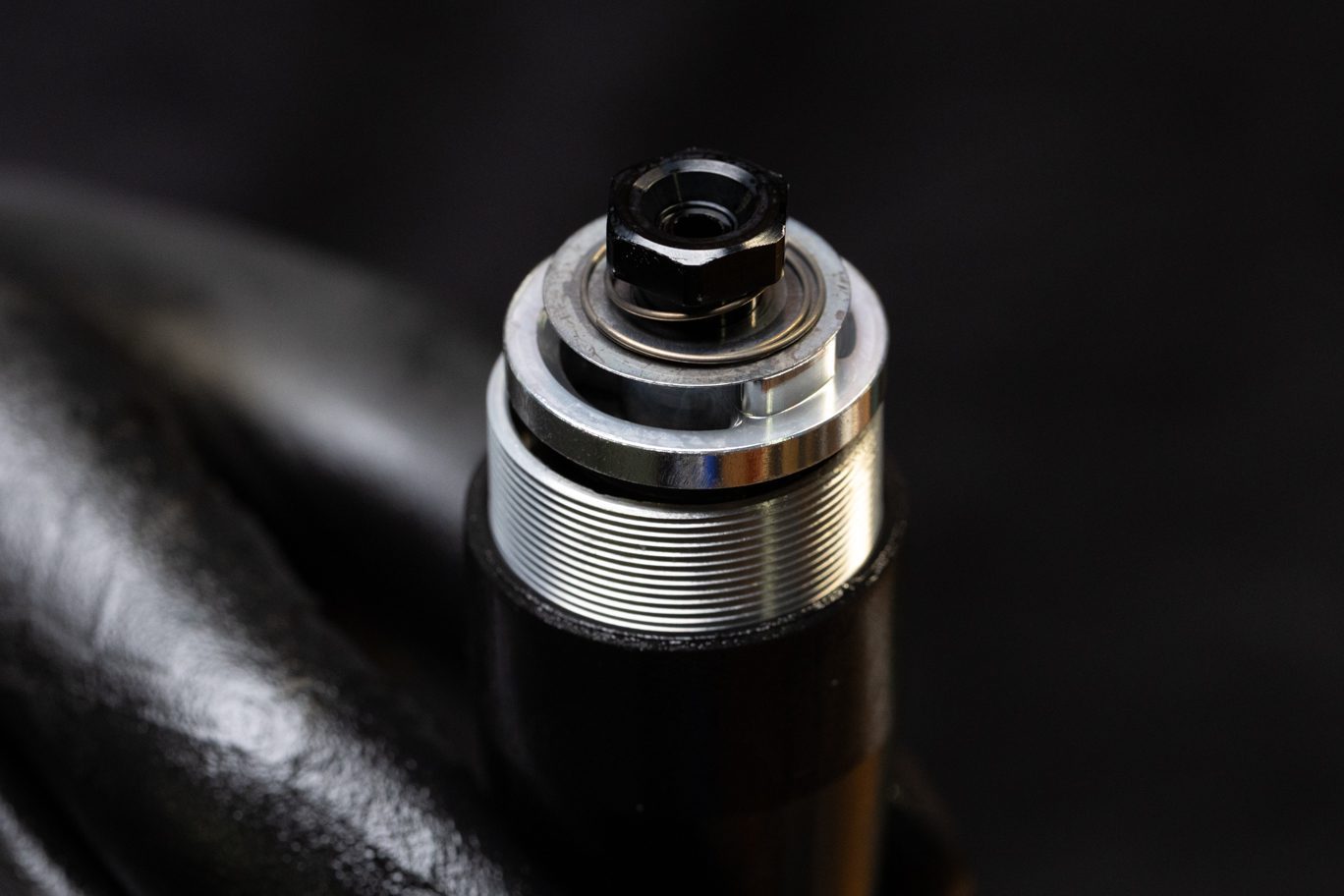
Step 10 – Compression Circuit Reassembly
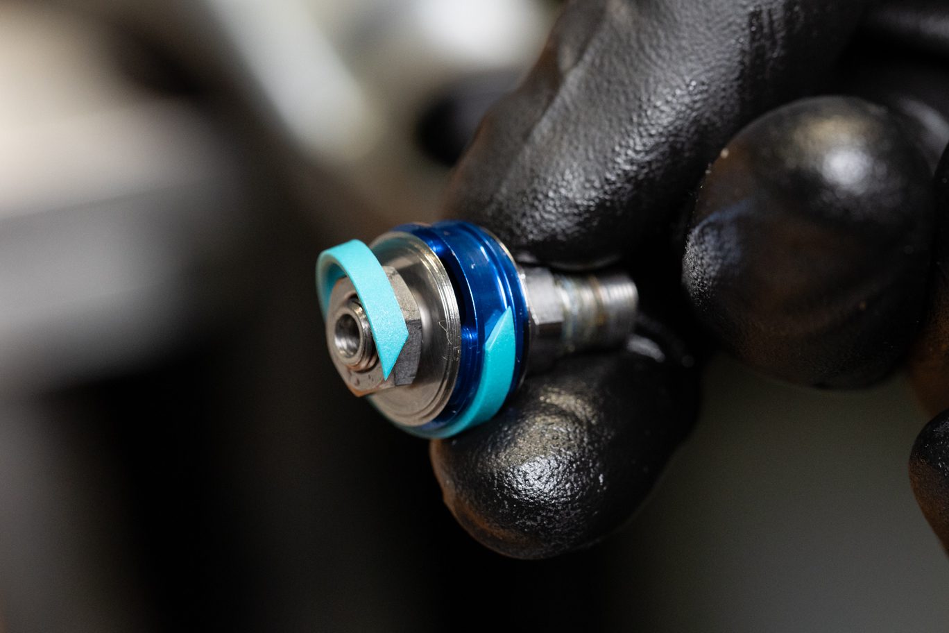
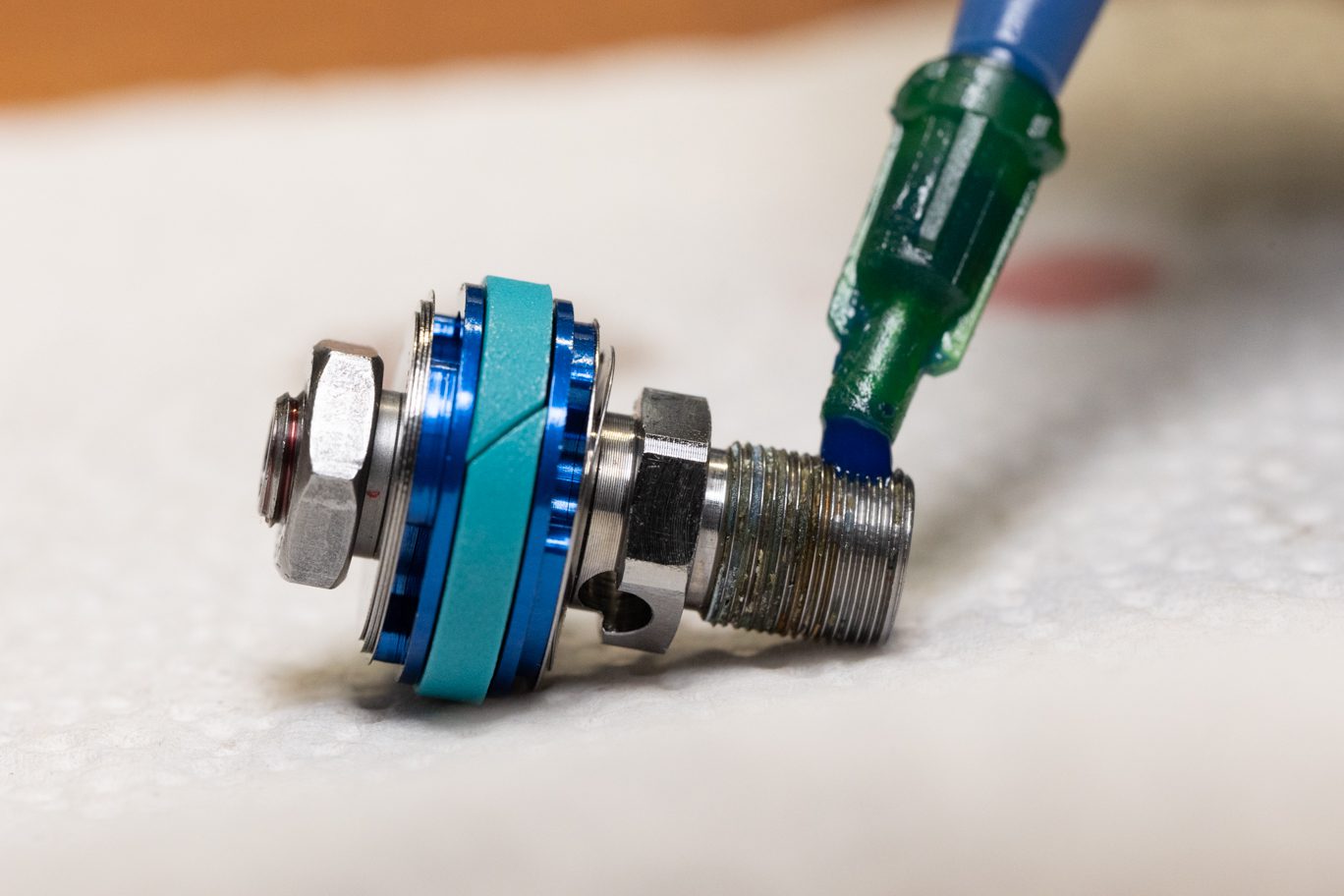
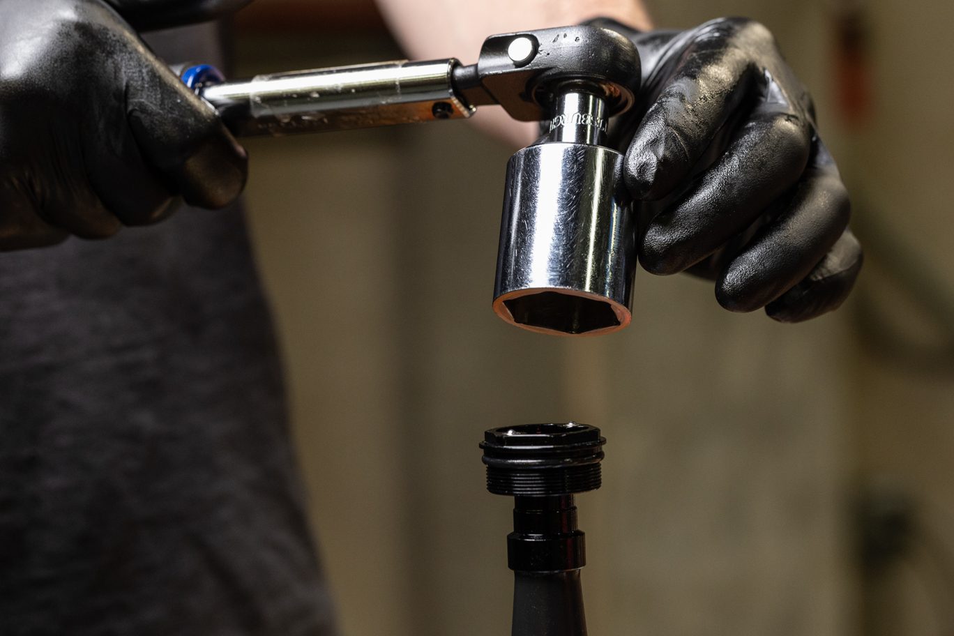
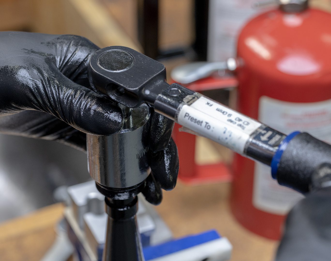
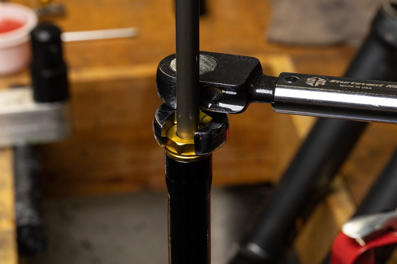
Apply damper oil to damper coupling. Thread damper coupling onto compression outer sleeve. Clamp damper coupling and torque damper top cap to 9 Nm using 30mm socket. Recheck that the helix still turns freely.
Applying Oil to Damper Coupling
Damper Coupling onto Outer Sleeve Install
Damper Coupling onto Outer Sleeve Installed
Tightening Damper Coupling onto Outer Sleeve
Damper Coupling Clamped
Tool to Top Cap
Damper Coupling Torque
Checking Helix Movement

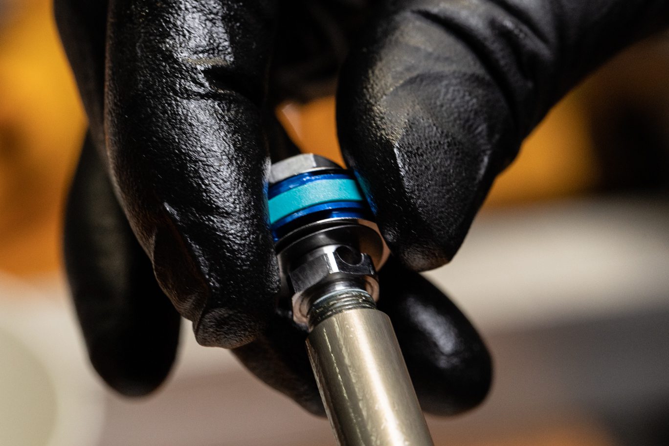
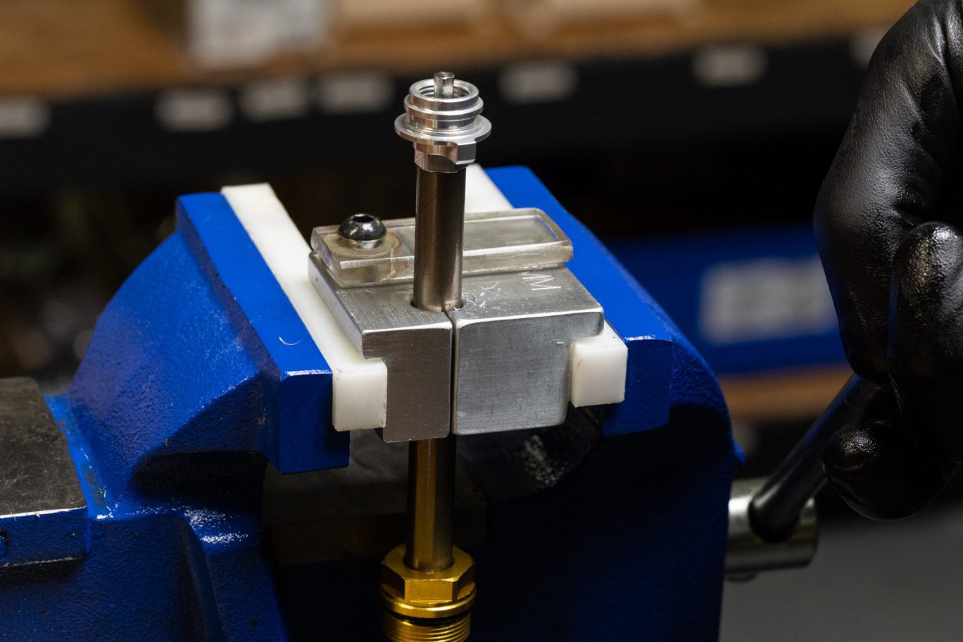
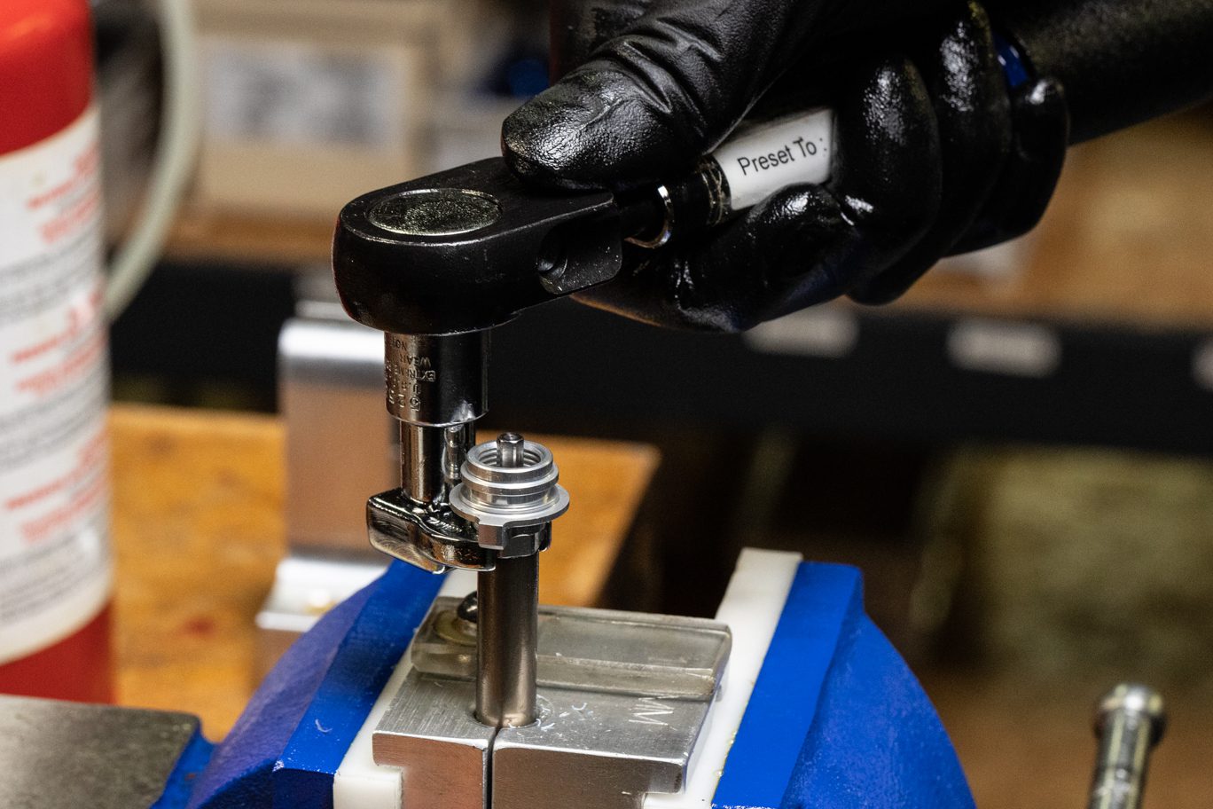
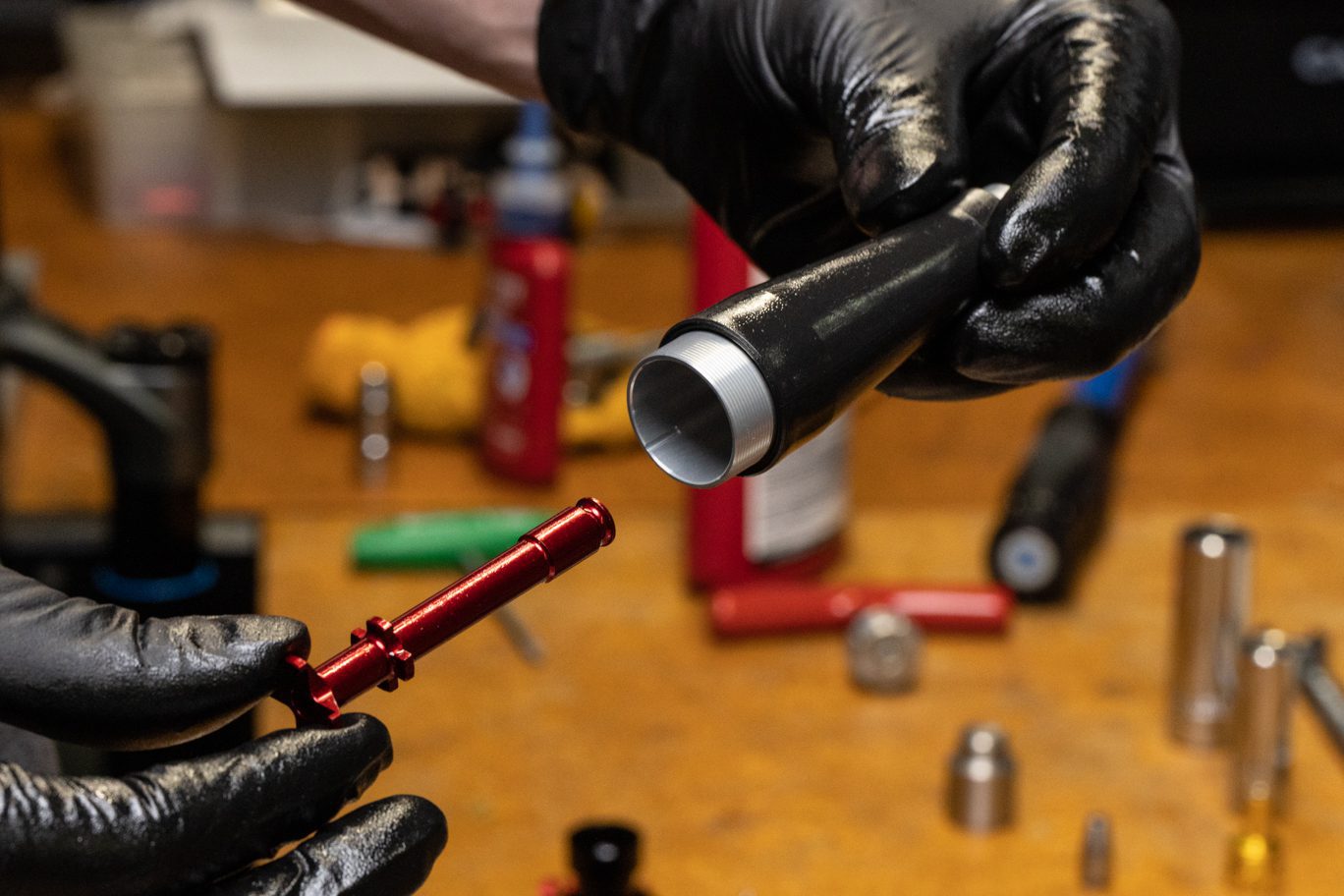
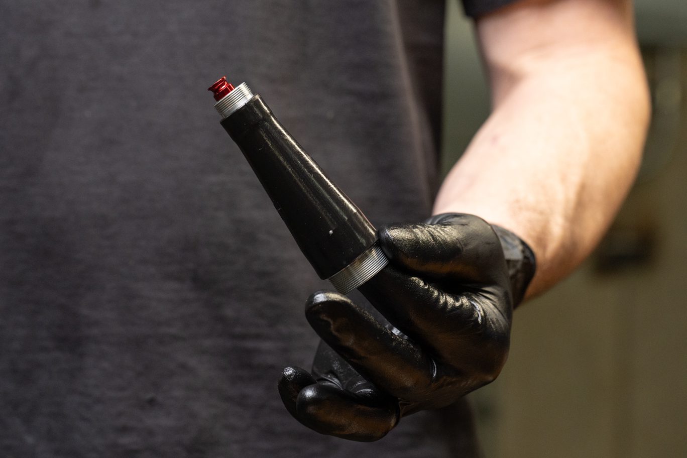
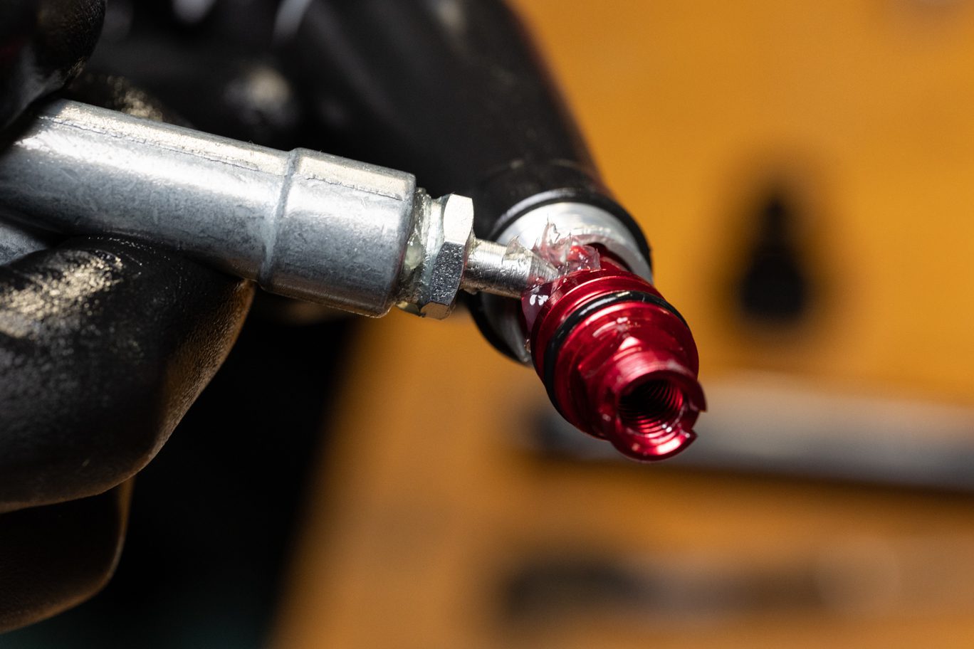
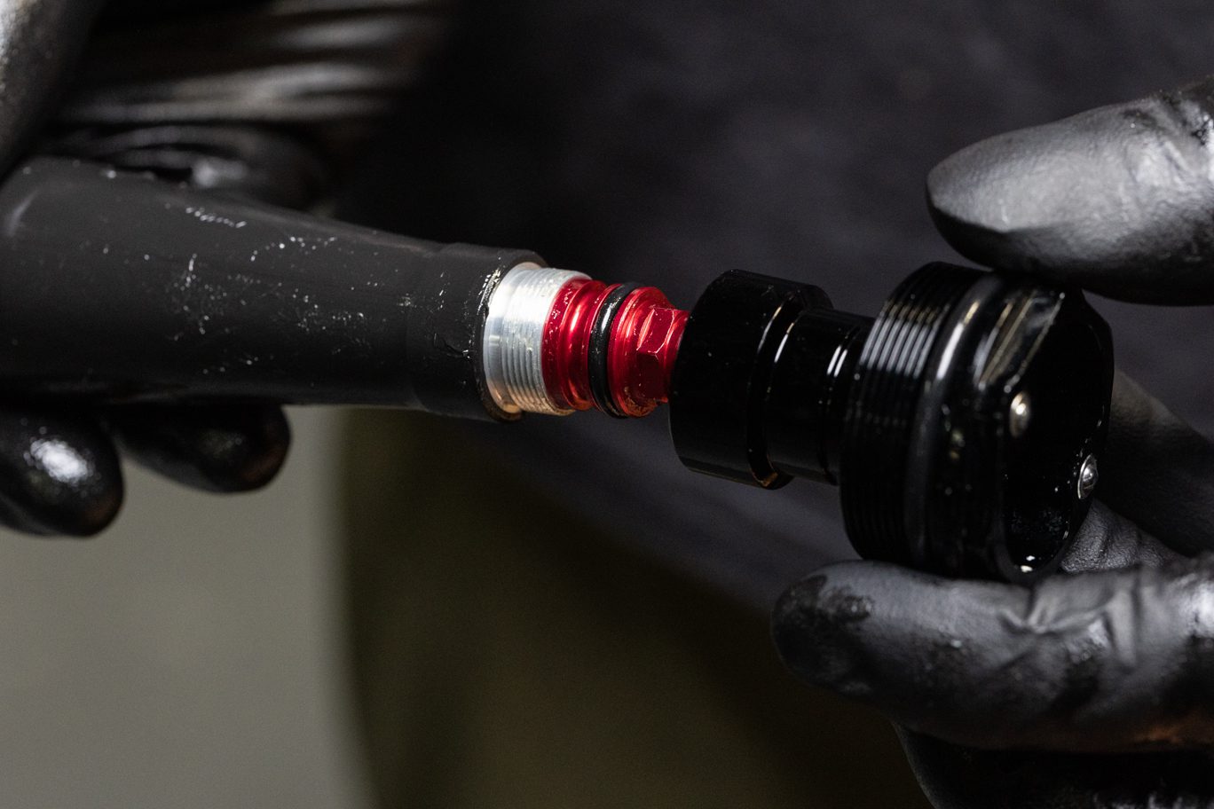
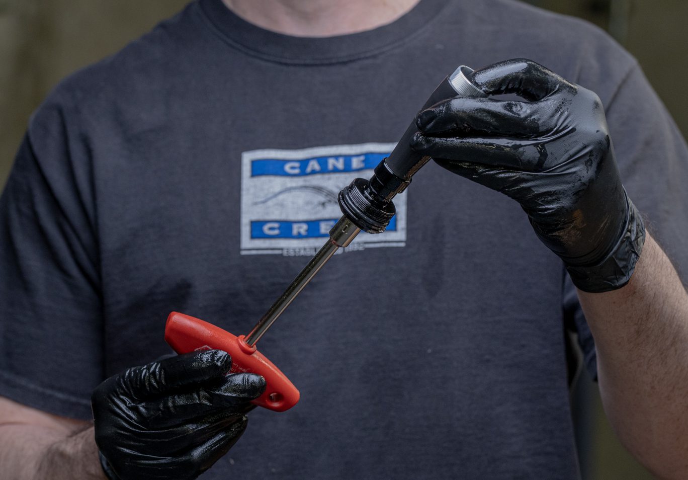
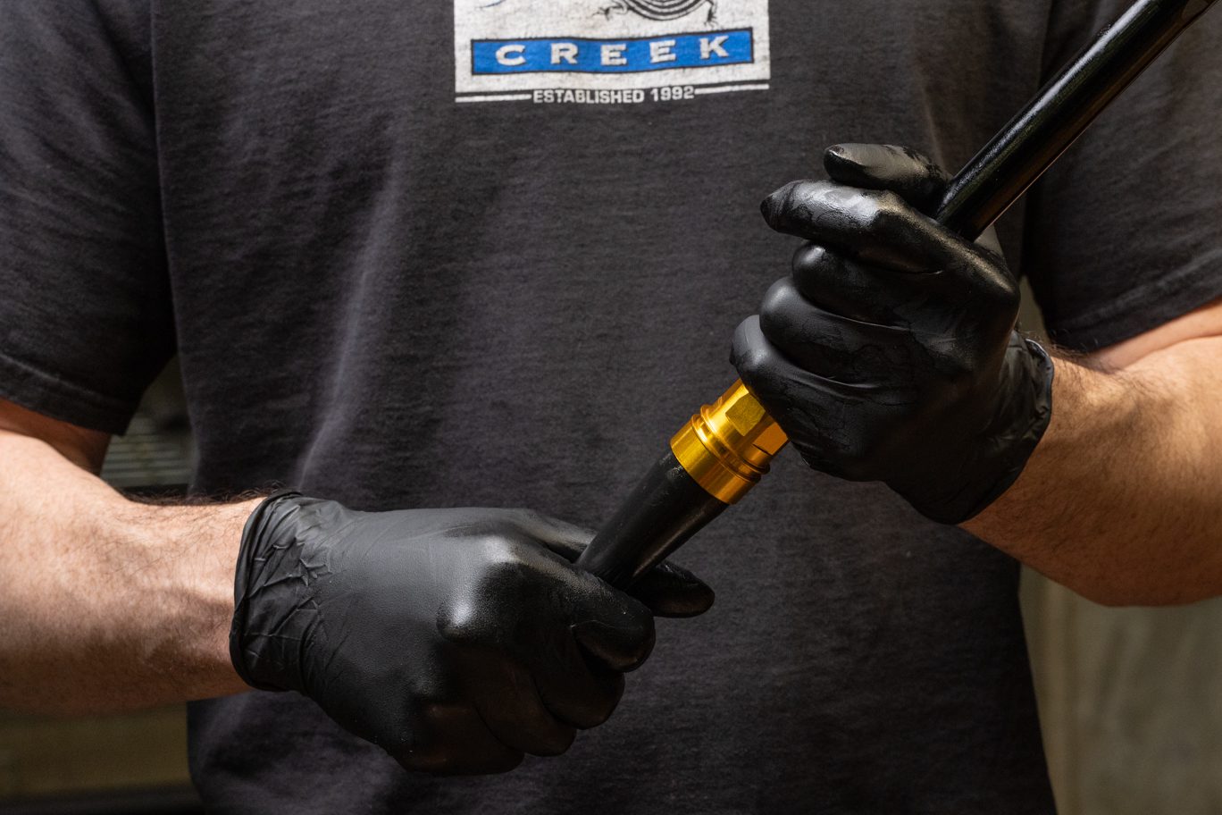
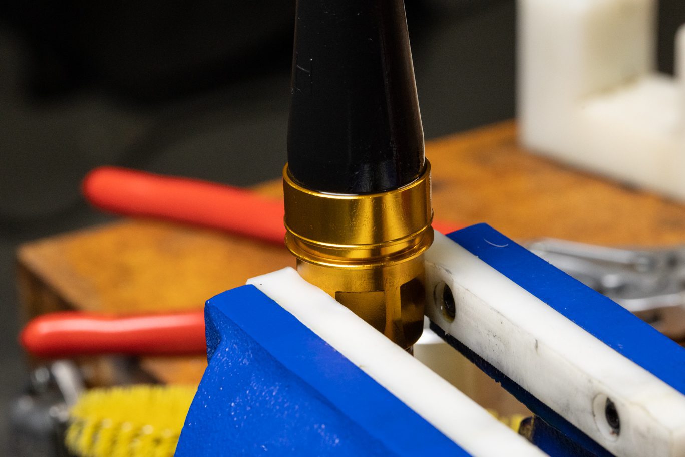
Step 11 – Rebound Circuit Install
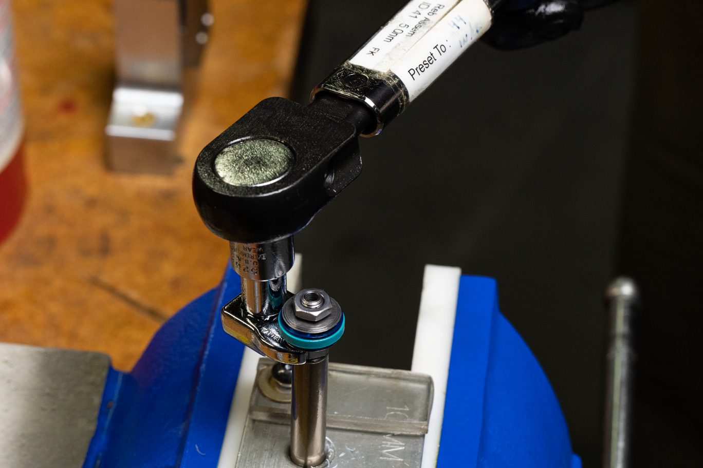
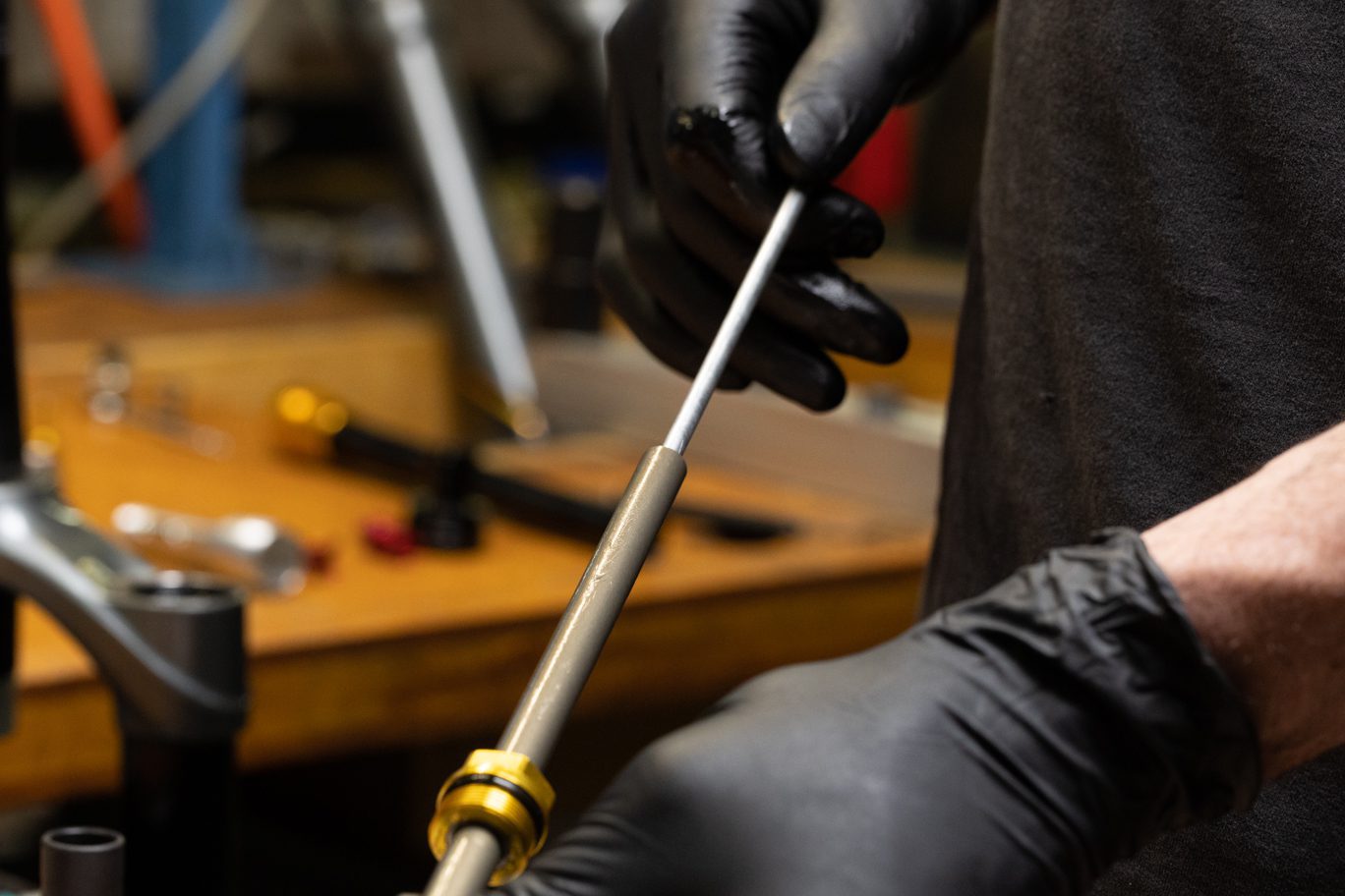
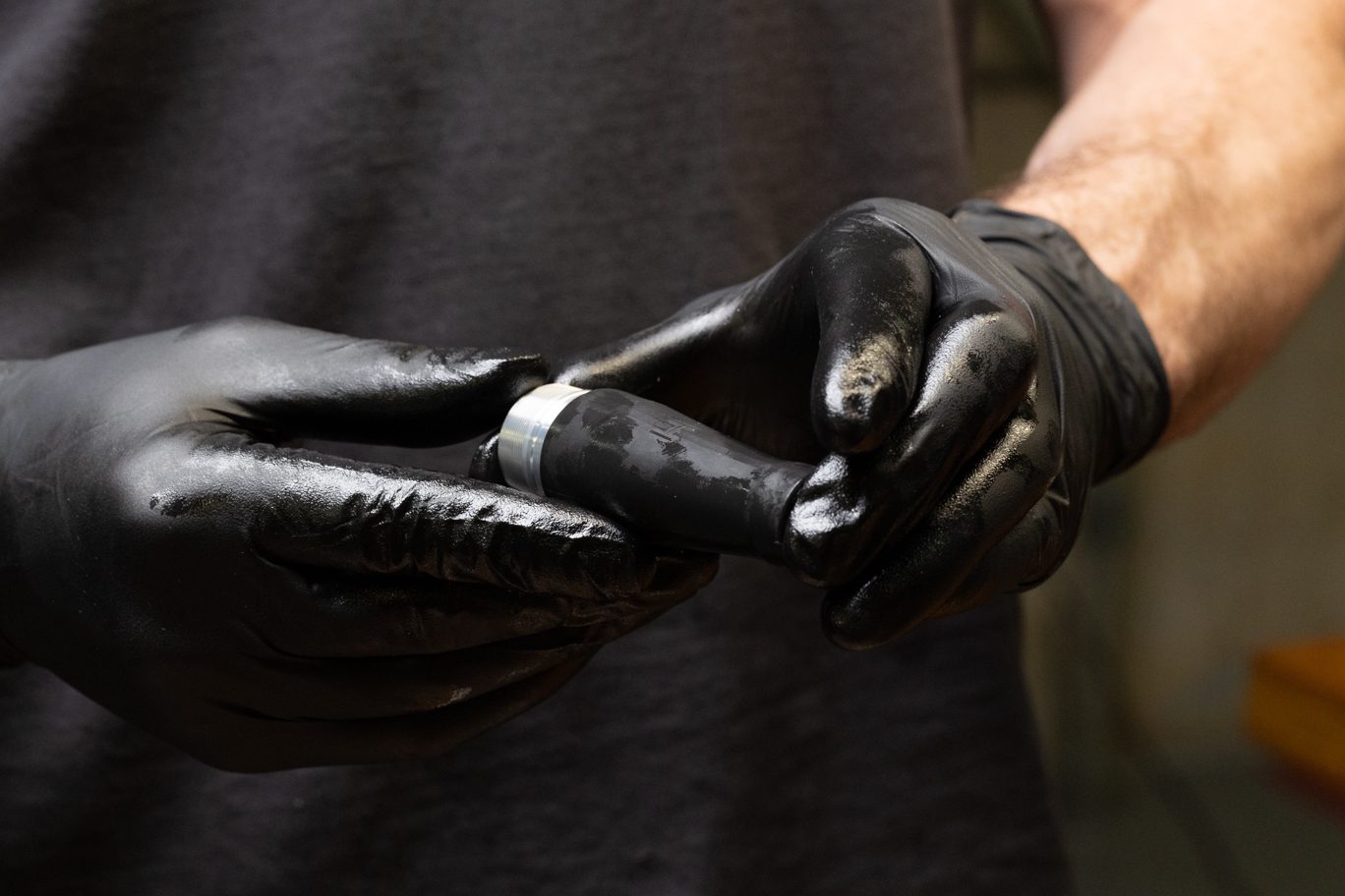
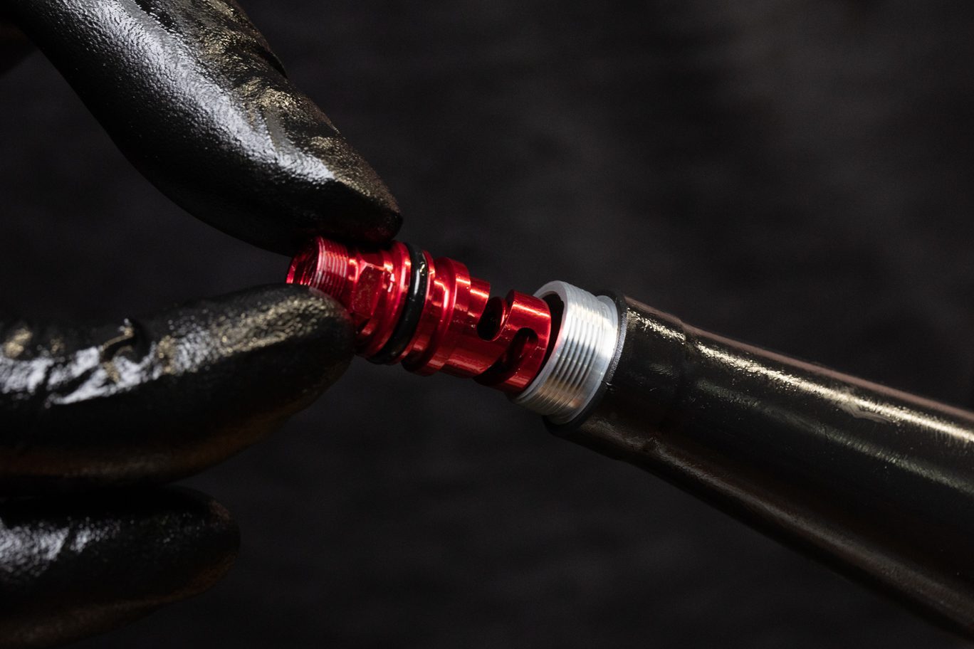
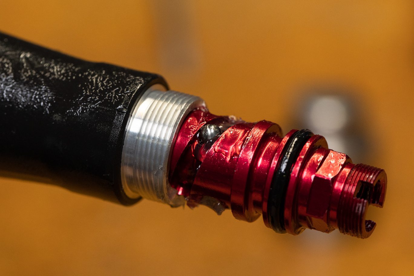
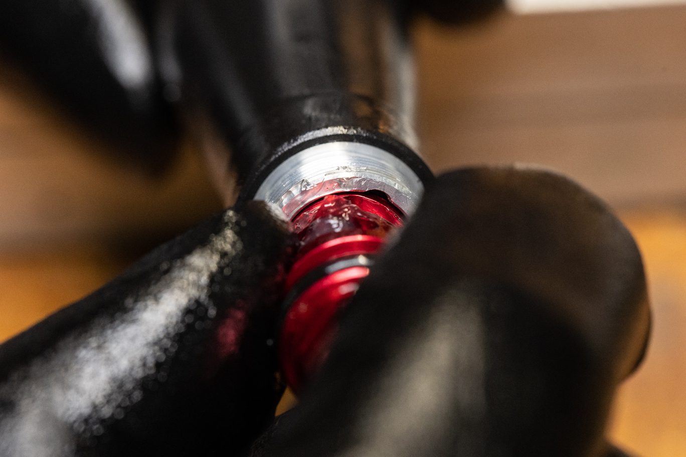
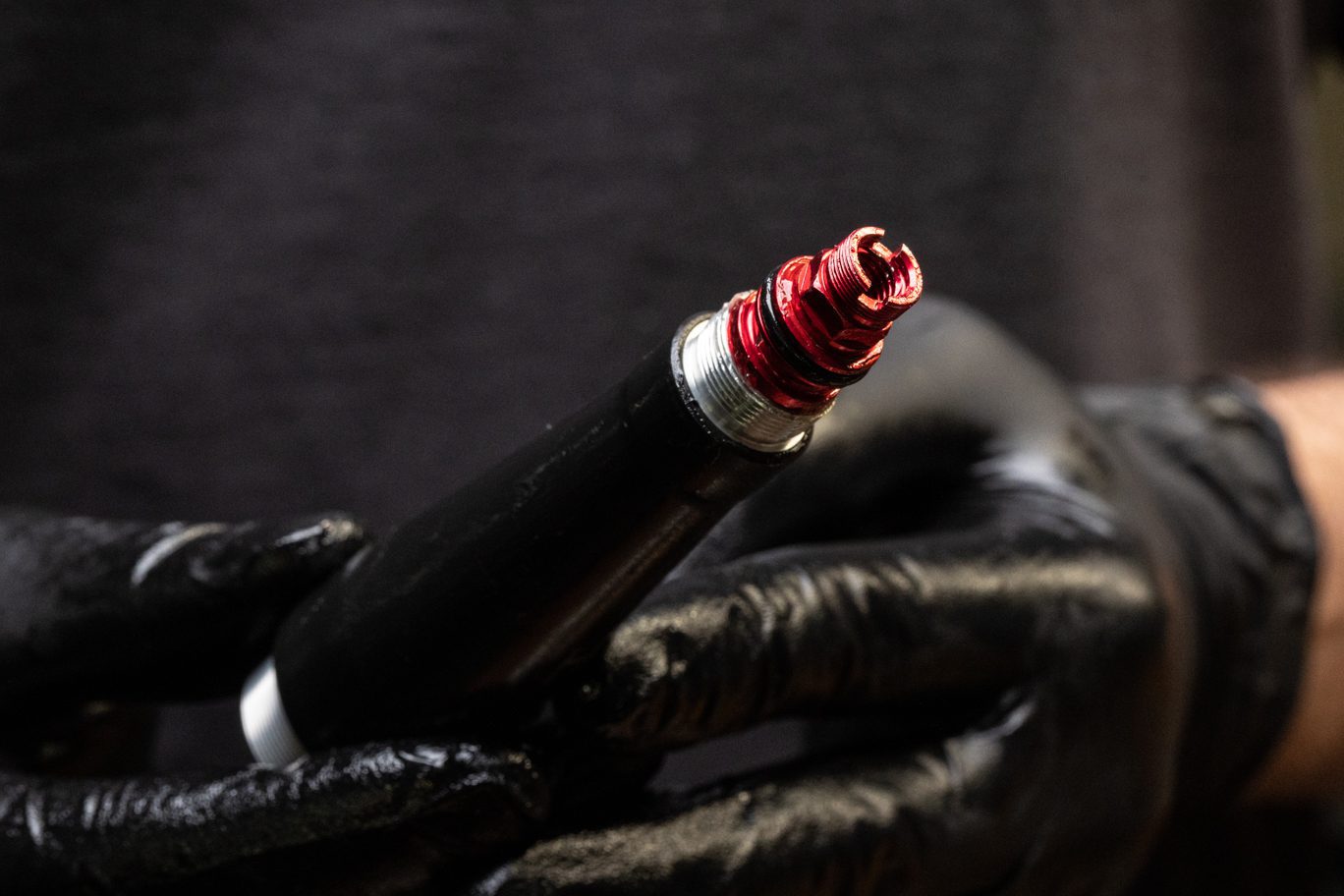
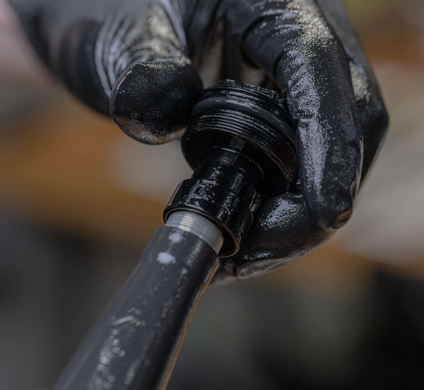
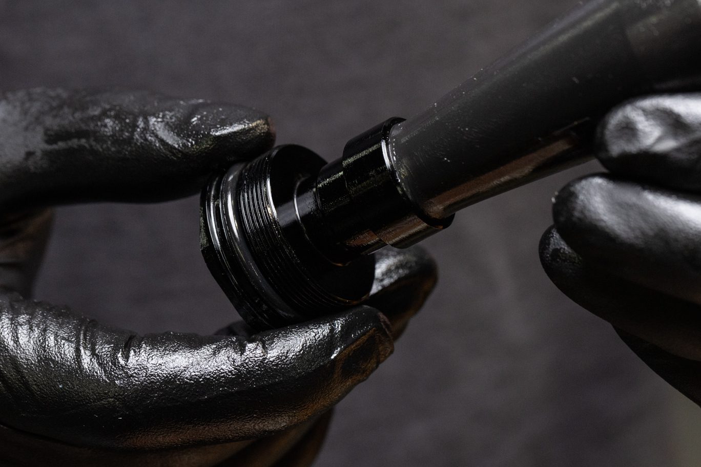
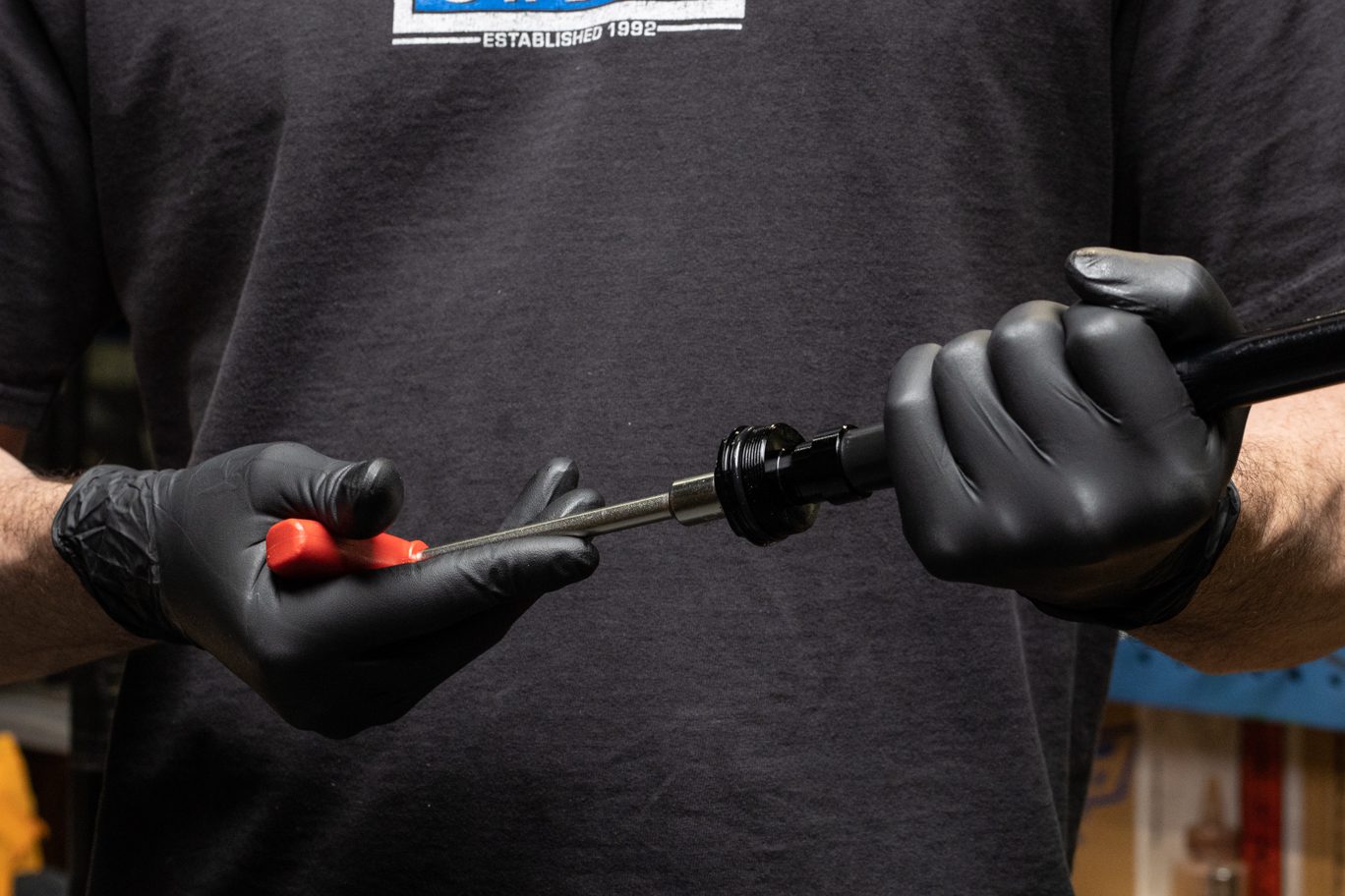
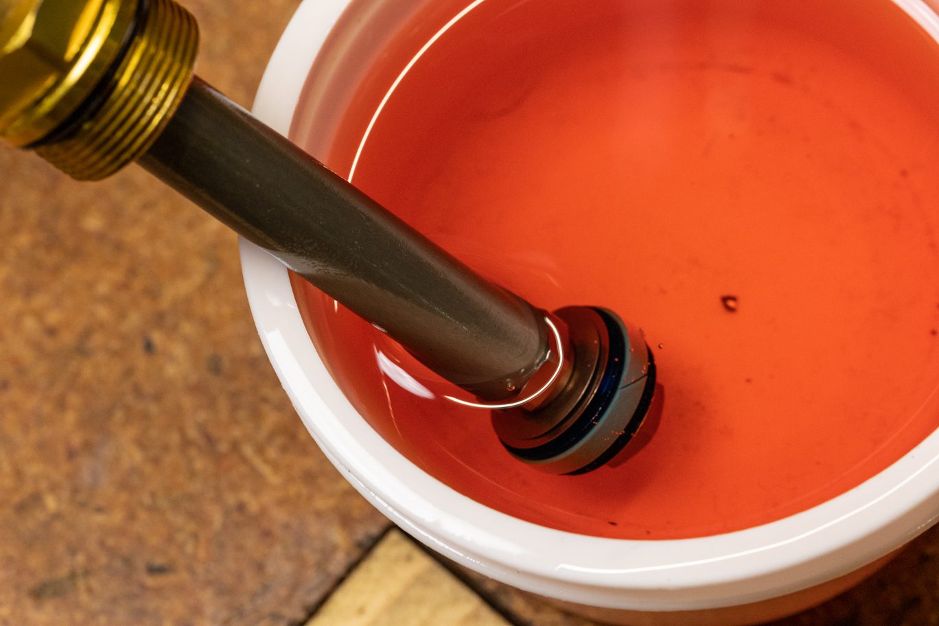
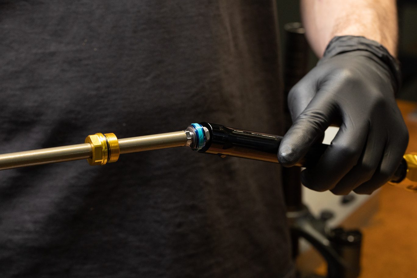
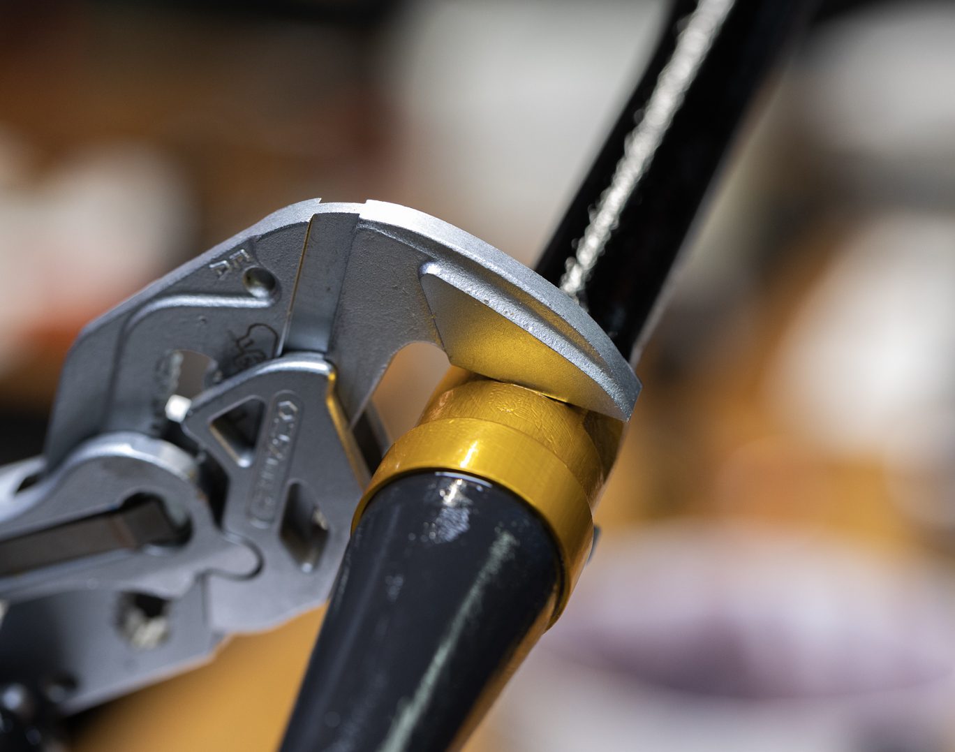
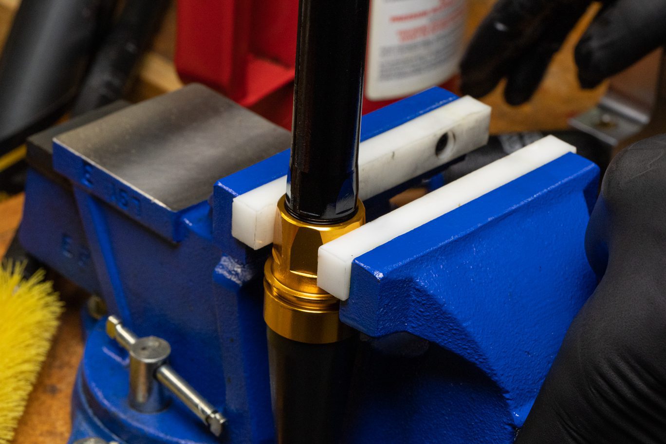
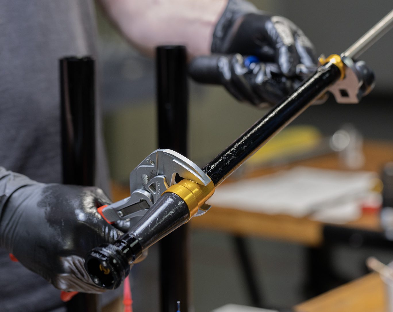
Coat rebound piston in damper oil. Insert rebound assembly into damper tube. Thread oil seal head into damper tube. Secure damper coupling using vise or Knipex and torque oil seal head to 13 Nm using 22mm crowfoot.
Coating Rebound Piston
Rebound Circuit Install
Rebound Circuit Installed
Clamping Damper Coupler (Knipex)
Clamping Damper Coupler (Vise)
Oil Seal Head Torque (Knipex)
Oil Seal Head Torque (Vise)
Continue to Part 3
Next