

DBKitsuma Air Complete 100 & 200 Hour Service Instructions (Part 3 of 4)
Mar 2022 orig., Jul 2023 rev.
Table of Contents
Recommendations and Warnings
Cane Creek recommends only trained suspension technicians perform service on all suspension, using all required tools and following all proper procedures. Anyone without access to the proper equipment or with any concerns on the procedures should defer to an authorized Cane Creek service center for service. Improper service can result in loss of performance or suspension failure. All Cane Creek shocks have pressurized nitrogen and oil, even coil shocks. Follow the service procedures exactly as written to avoid possible injury or harm to the suspension. Always wear eye protection while performing suspension service.
Please dispose of all waste products and materials through proper channels to avoid contamination of the environment.
Any damage or issues resulting from improper service will not be covered by warranty. If you have a shock still in its original warranty period and do not wish to void your warranty, please contact an authorized Cane Creek service center.
These service instructions cover the basic service procedures using standard service kits. If your suspension requires parts beyond standard replacement parts – shaft, damper tubes, end eyes – please consult your authorized Cane Creek service center or contact us at our Cane Creek Support Center.
Service Notes
The Kitsuma Air and Coil share many service steps. Additionally, the Standard and Trunnion variants of both models have identical service procedures other than where to clamp the cylinder head. Some images in these instructions may not be identical to the valve body or outer damper tube on the Kitsuma Air, but process is the same for the shock in the image and the shock on your bench.
100 vs. 200 hour service
The only difference between the 100 hour service and the 200 hour service is whether to service or replace the Air Oil Seal Head and the Main Oil Piston. At 100 hours, those can be cleaned, serviced and reinstalled. At 200 hours, they should be replaced. If uncertain on hours, check for wear on the dual bushings inside the Air Oil Seal Head and on the piston band on the Main Oil Piston. When in doubt, replace both.
Service Kits
BCD0337 – Kitsuma Air Complete 100 Hour Rebuilt Kit (w/ Bladder)
OR
BCD0339-01 – Kitsuma Air Complete 200 Hour Rebuild Kit (w/ Bladder) – includes new Air Oil Seal Head & Main Oil Piston
BCD0169 – Bladder Res End Cap (if replacing older IFP system)
Required Cane Creek Tools
ACD0354 – Bladder Res End Fill Tool
AAD1361-01 – DBCoil/ DBAir – Oil Fill Needle Adapter
DBT016 – DB Gas Fill Needle
AAD0555 – 8mm & 9.5mm Shaft Clamp
AAD2465 – Kitsuma Valve Seat Tool
ACD0322 – Kitsuma Low Speed Detent Funnel
BAD1298 – DB 9.5mm Shaft Bullet
ACD0334 – Kitsuma Air Oil Seal Head Tool
BCD0344 – Kitsuma/DBair/DBair IL Air Seal Head Tool
DBT012 – DB IFP Setting Tool
Additional Tools & Supplies
Allen wrenches – 3 & 4mm
Torx wrenches – T10 & T20
Sockets – 4, 8 & 13mm
Crowfoot wrenches – 1/2″ & 32mm
9.5mm Shaft Bullet
Torque wrenches
Knipex pliers
Pick
Strap wrench
Suspension Grease
PolyLube Grease
Motorex 4wt Racing Fork Oil
Royal Purple 10w-30
Vacuum Oil Fill Machine
Nitrogen Fill System
Torque, Loctite, Oil & Nitrogen Specs
Torque & Loctite Chart
| Part | Torque Spec | Loctite Spec |
|---|---|---|
| Shaft Bolt | 5 Nm | 243 (Blue) |
| Outer Damper Tube | Tight | 263 (Red) |
| Valve Seat | 4.8 Nm | None |
| High Speed Adjuster | 7 Nm | None |
| Climb Switch Screw | 1.2 Nm | 243 (Blue) |
| Oil Seal Head | 22 Nm | None |
| End Eye | 4.8 Nm | 243 (Blue) |
| Inner Air Can/Air Seal Head | 22.6 Nm | None (PolyLube) |
Oil Chart
| Oil Location | Oil Type | Oil Amount |
|---|---|---|
| Air Can | Royal Purple 10w-30 | 5 mL |
| Damper Fill | Motorex 4wt Racing Fork Oil | Fill to 3 Bars |
Nitrogen Chart
| Nitrogen Location | Nitrogen Pressure |
|---|---|
| Valve Body | 11 - 12 Bars |
Damper Reassembly
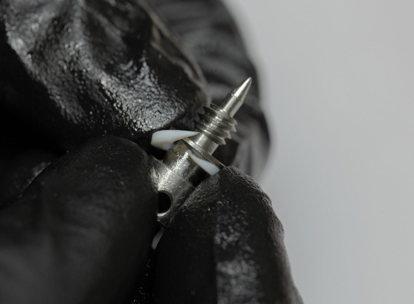
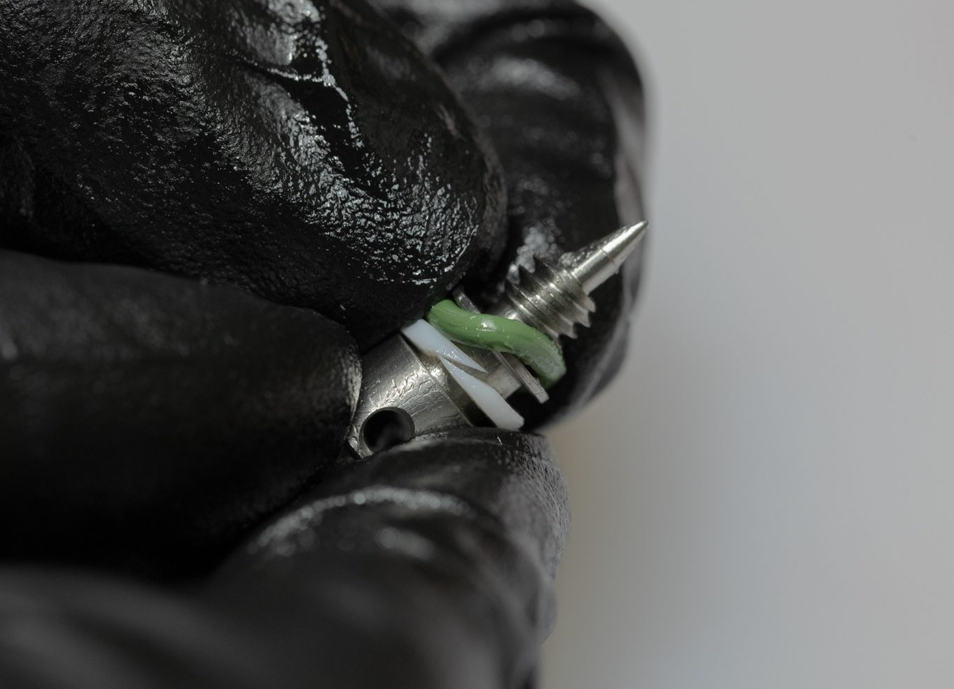
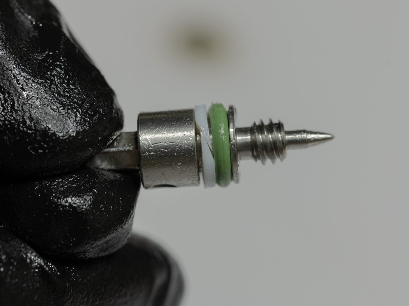
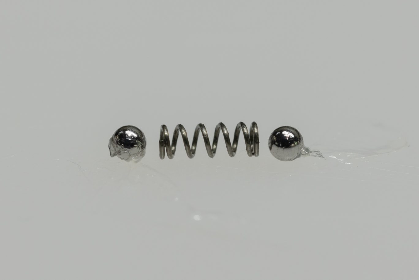
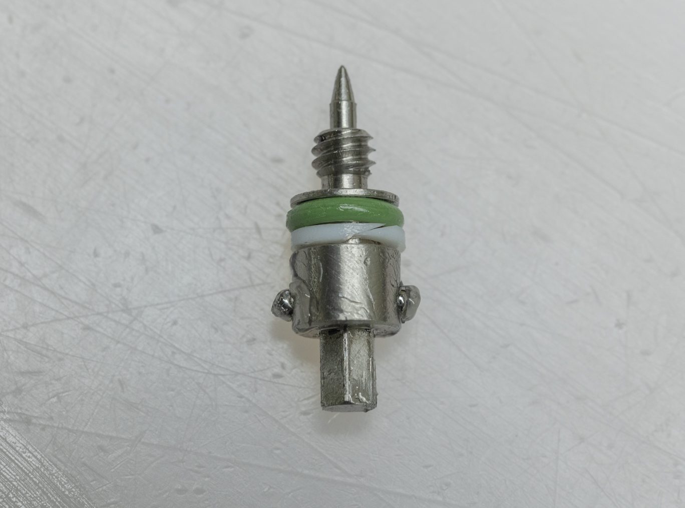
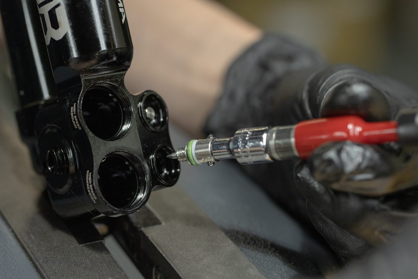
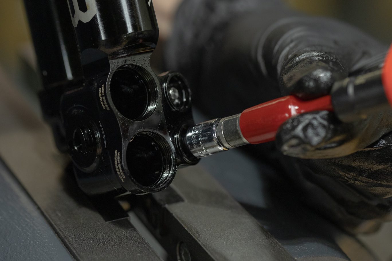
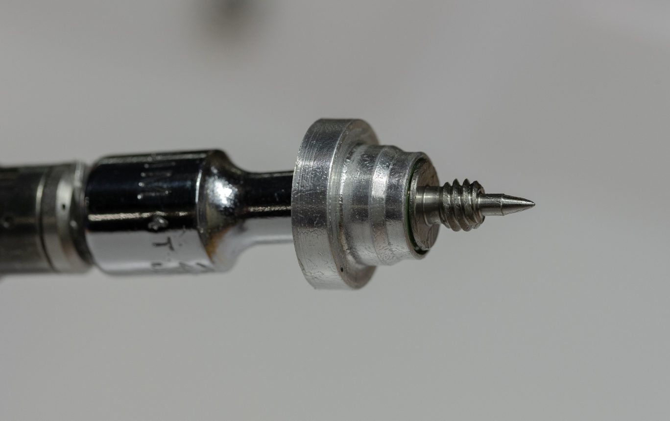
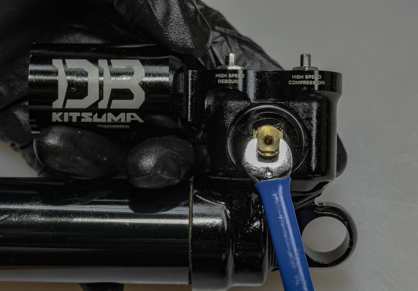
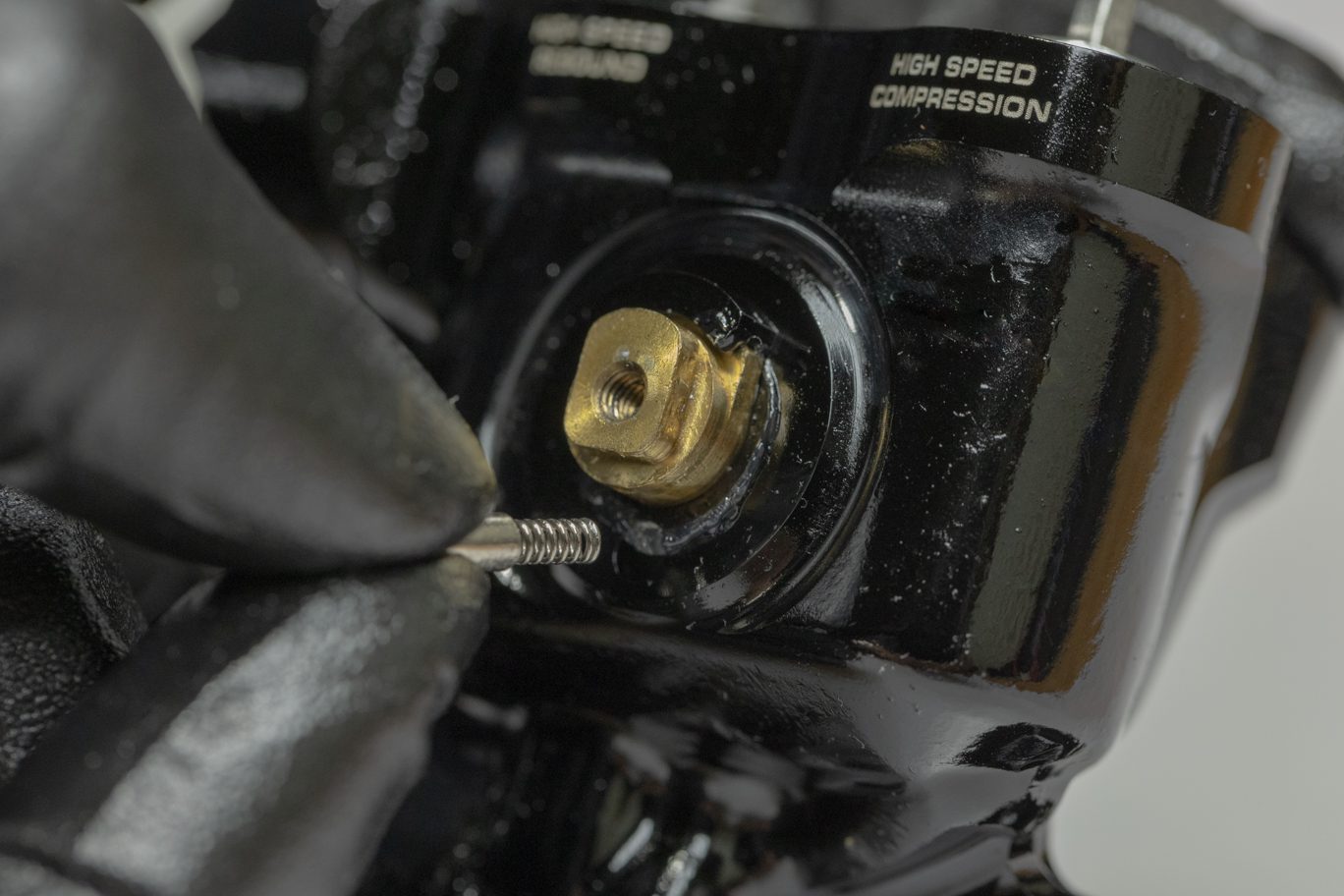
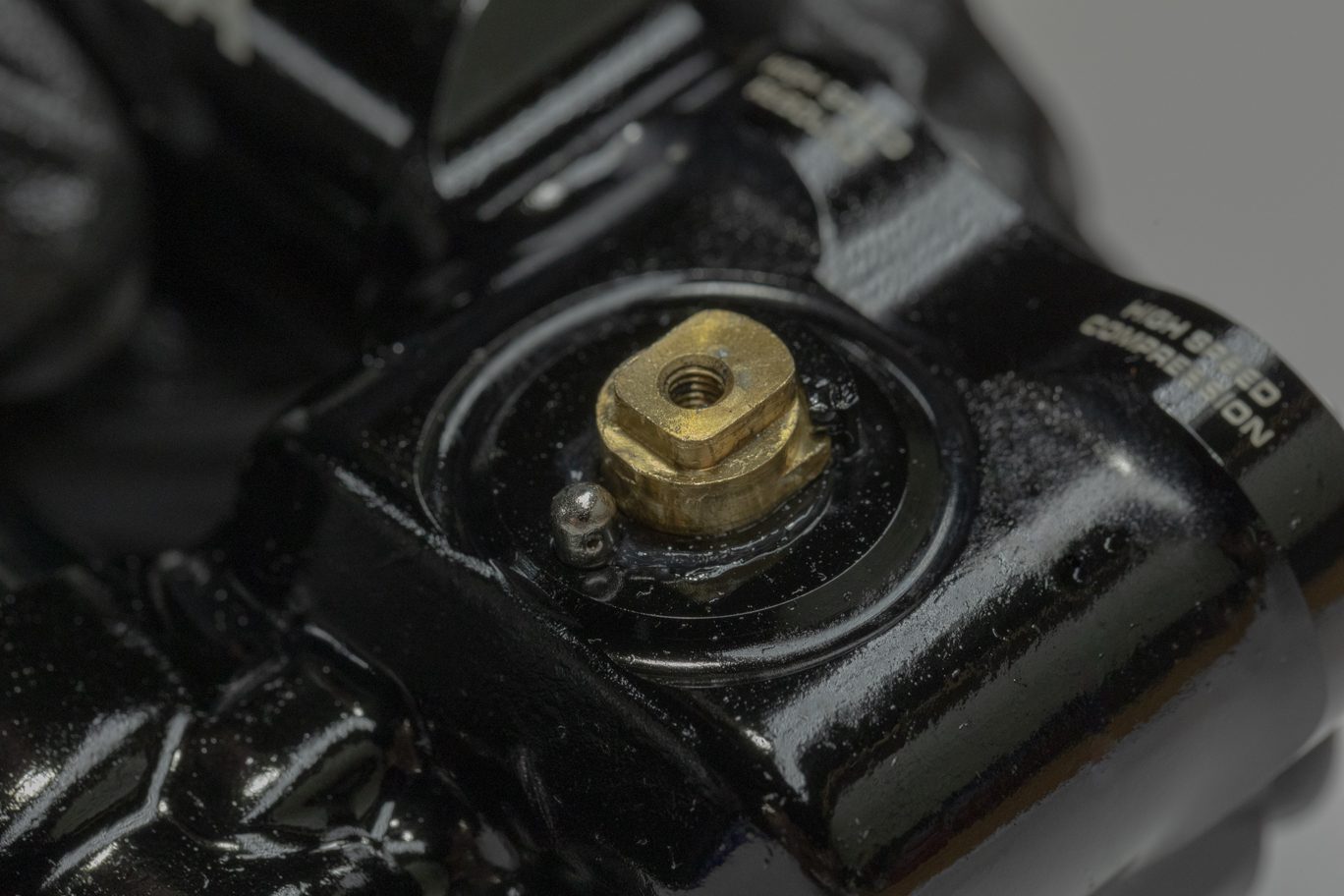
Step 1 – Low Speed Needles Install
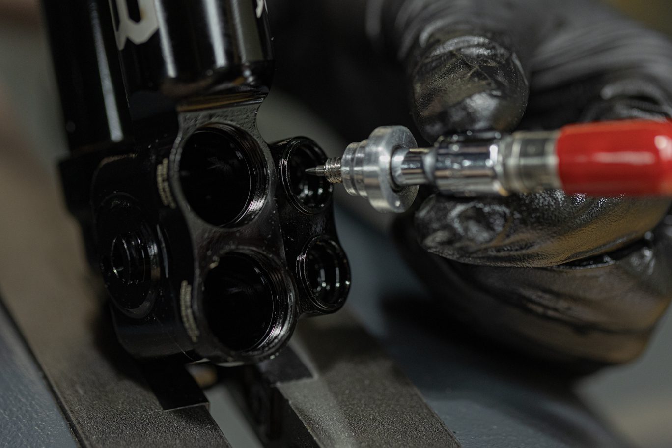
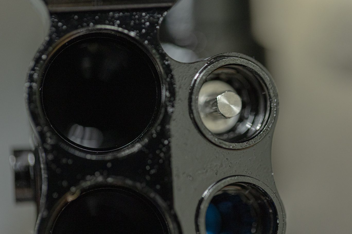
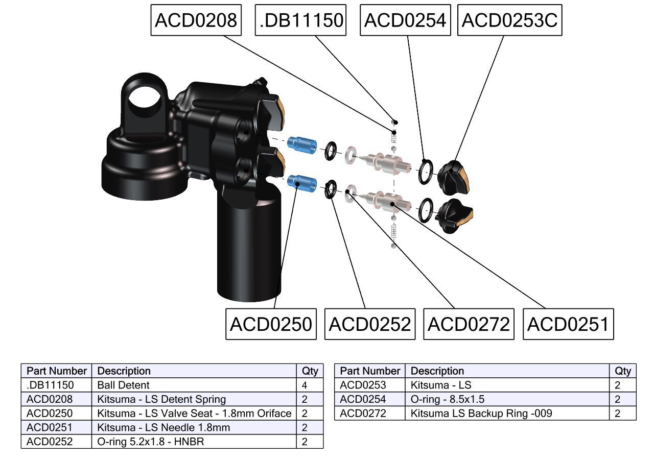
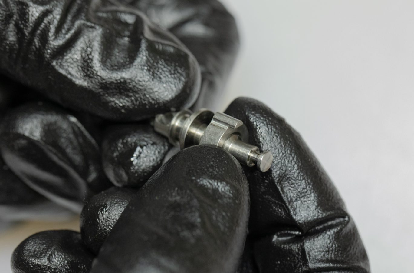
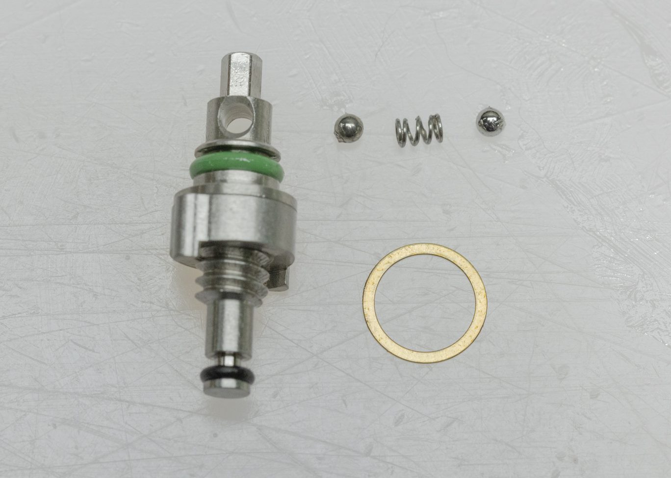
Install new back up ring (ACD0272) and lightly greased o-ring (ACD0252) on low speed needles. Using grease, reinstall spring and detent balls into low speed needles. Install low speed needles into valve body. Needle detent funnel (ACD0322) maybe used to ease install. Thread until bottomed then back out to ensure detents engagement. Then lightly bottom out the needle again.
Low Speed Needle Back Up Ring Install
Low Speed Needle O-Ring Install
Low Speed Needle O-Ring & Back Up Ring Installed
Low Speed Needle Detent Balls & Spring
Complete Low Speed Needle
Low Speed Needle Install 1
Low Speed Needle Install 2
Low Speed Needle w/ Funnel Tool
Low Speed Needle Install w/ Funnel Tool
Low Speed Needle Installed
Exploded Low Speed Needle Assembly

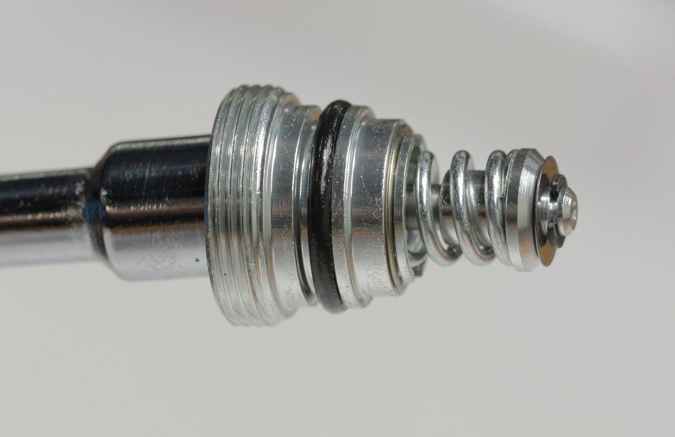
Step 2 – High Adjuster Shuttle Assembly
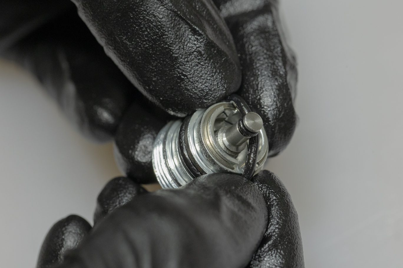
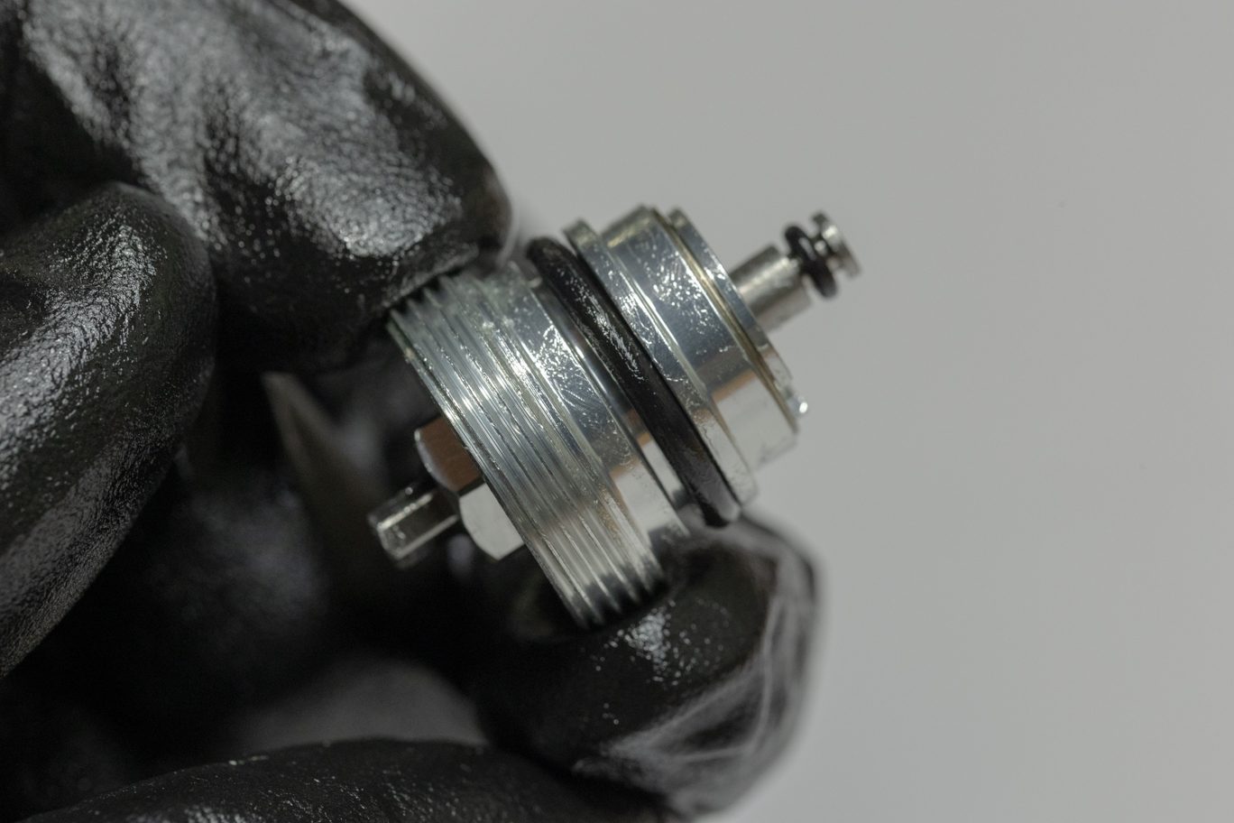
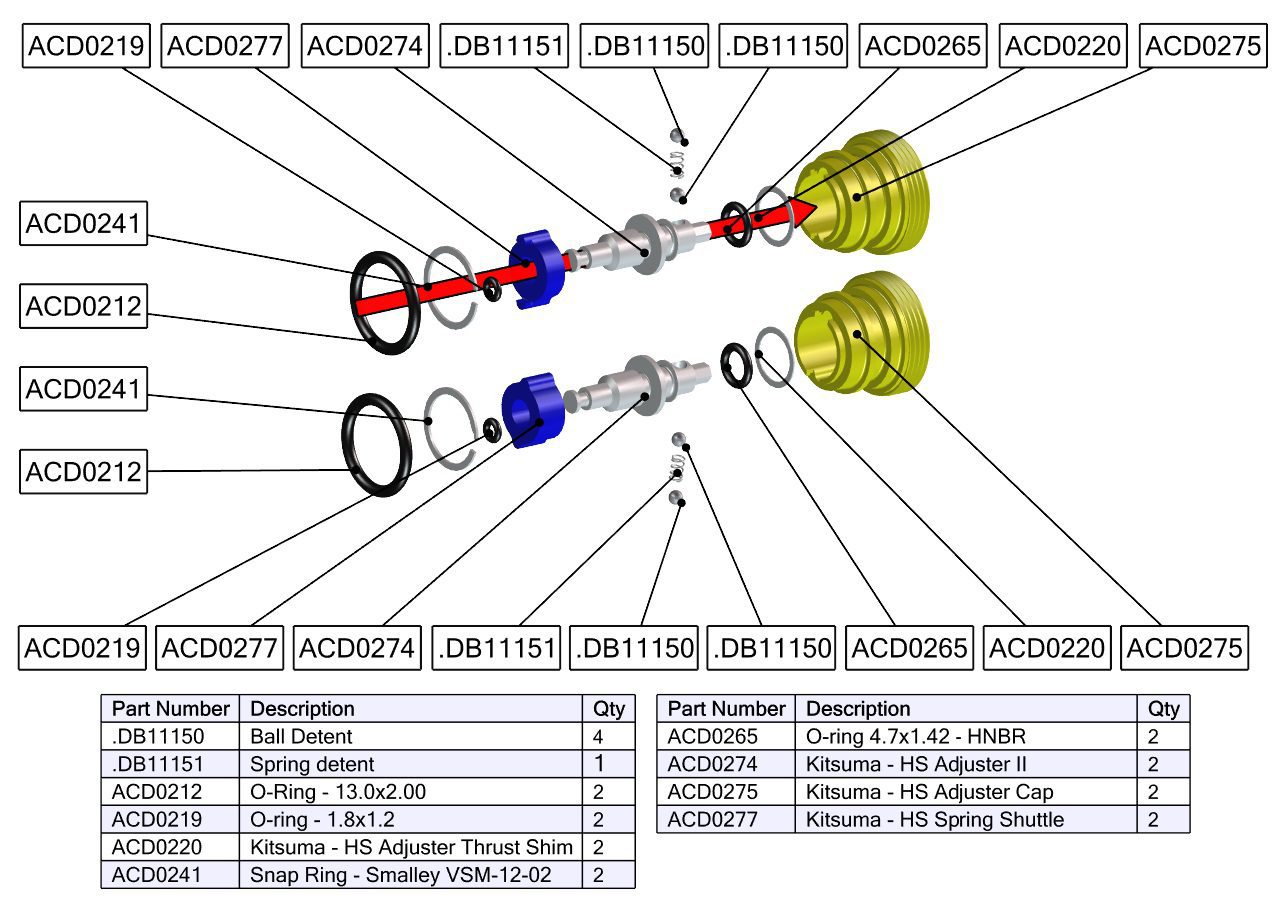
Thoroughly clean high speed adjustor threads and shuttle. Install shuttle onto adjustor. Note the orientation of the shuttle. Lightly grease and install high speed adjustor o-ring (ACD0265) and poppet o-ring (ACD0219).
TSB038 – Kitsuma HSR Revalve
Threading Shuttle onto High Speed Adjuster
Shuttle on High Speed Adjuster
Adjuster O-Ring Install
Adjuster O-Ring Installed
Poppet O-Ring Install
Assembled High Speed Adjuster
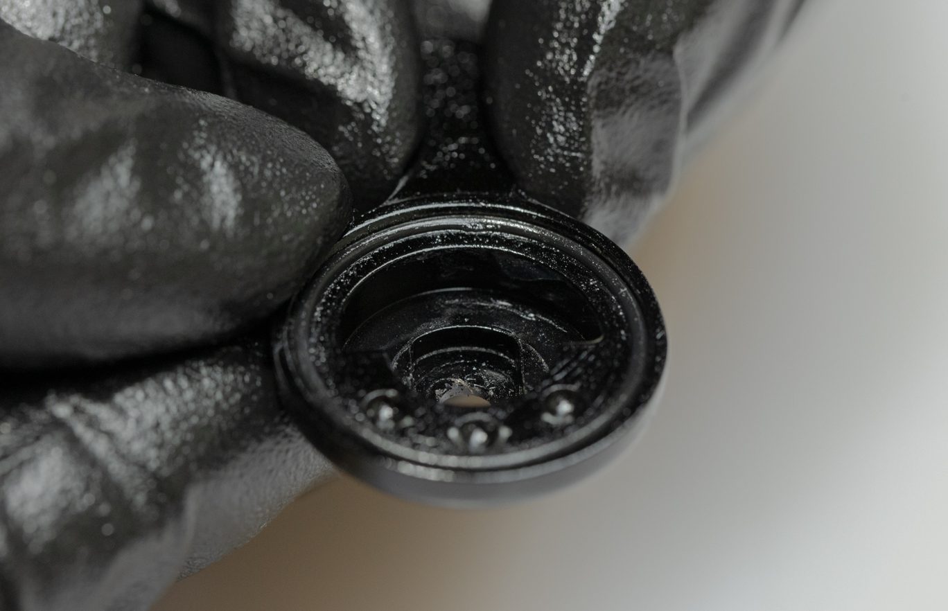
Step 3 – High Speed Adjuster Housing Assembly
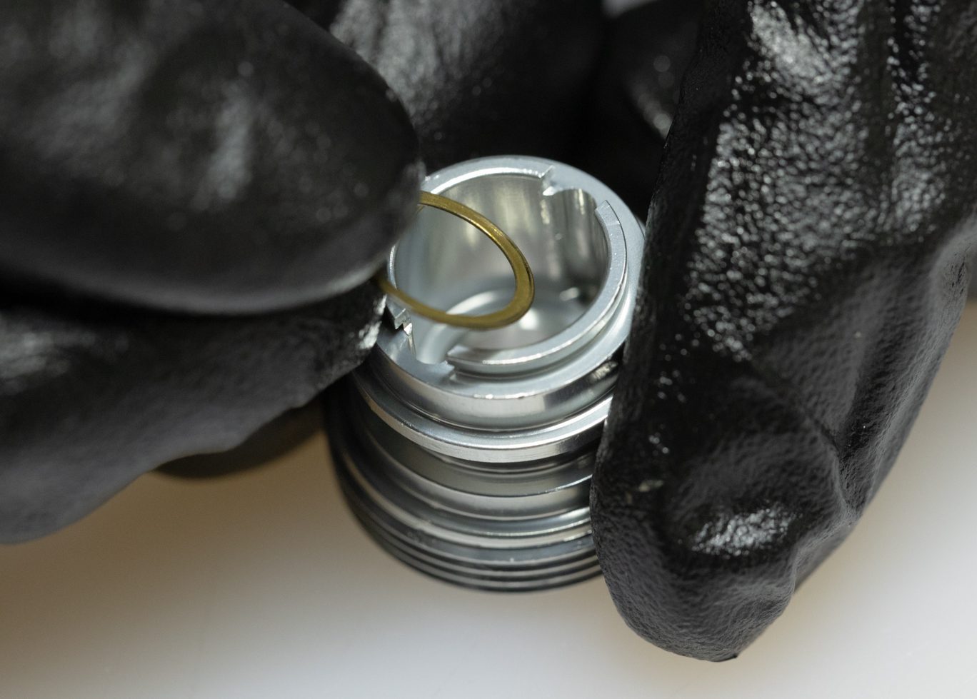
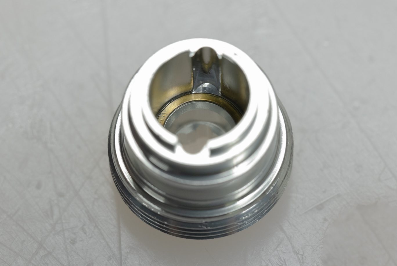
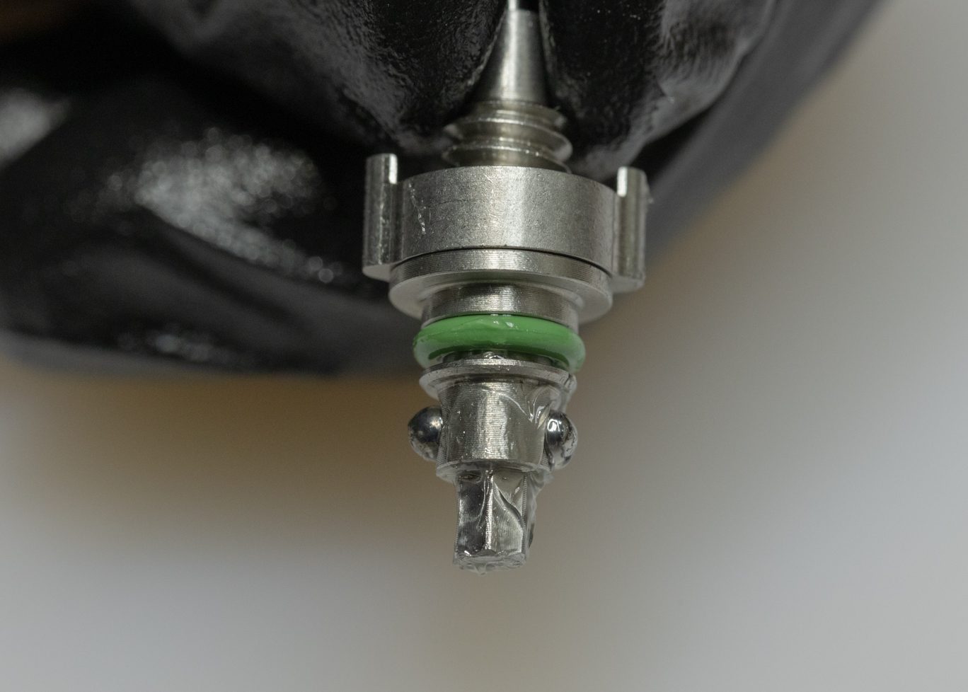
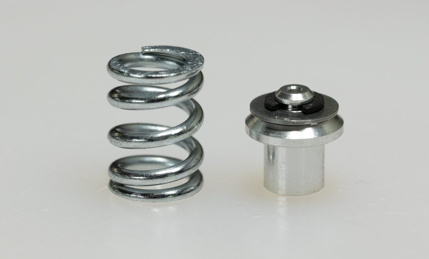
Insert gold shim into bottom of high speed adjustor housing. Using grease, reinstall spring and detent balls into high speed adjuster. Insert assembled high speed adjustors into high speed adjutor housing. Install circlip. Lightly grease and install high speed adjustor housing o-ring (ACD0212).
High Speed Adjustor Before Housing Install
Housing Gold Shim Install
Housing Gold Shim Installed
High Speed Adjuster Detent Balls & Spring Installed
High Speed Adjuster Inserting into Housing
High Speed Adjuster Inserted into Housing
High Speed Adjuster Housing Circlip Install
High Speed Adjuster Housing Circlip Installed
High Speed Adjuster Housing O-Ring Install
High Speed Adjuster Housing O-Ring Installed
Exploded High Speed Adjuster Assembly
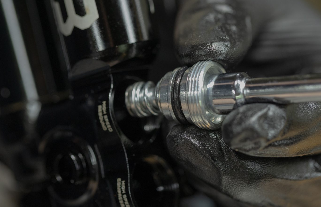
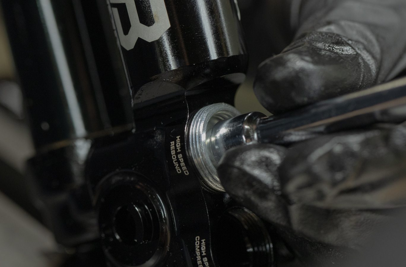
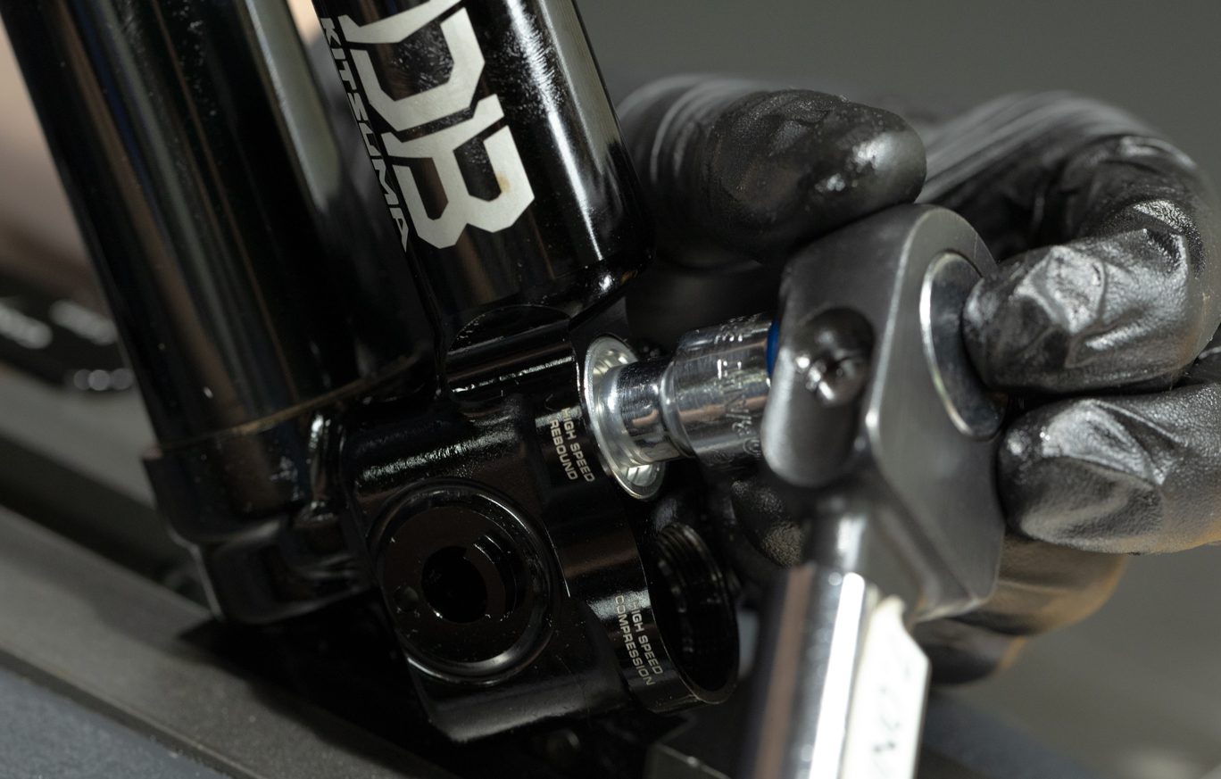
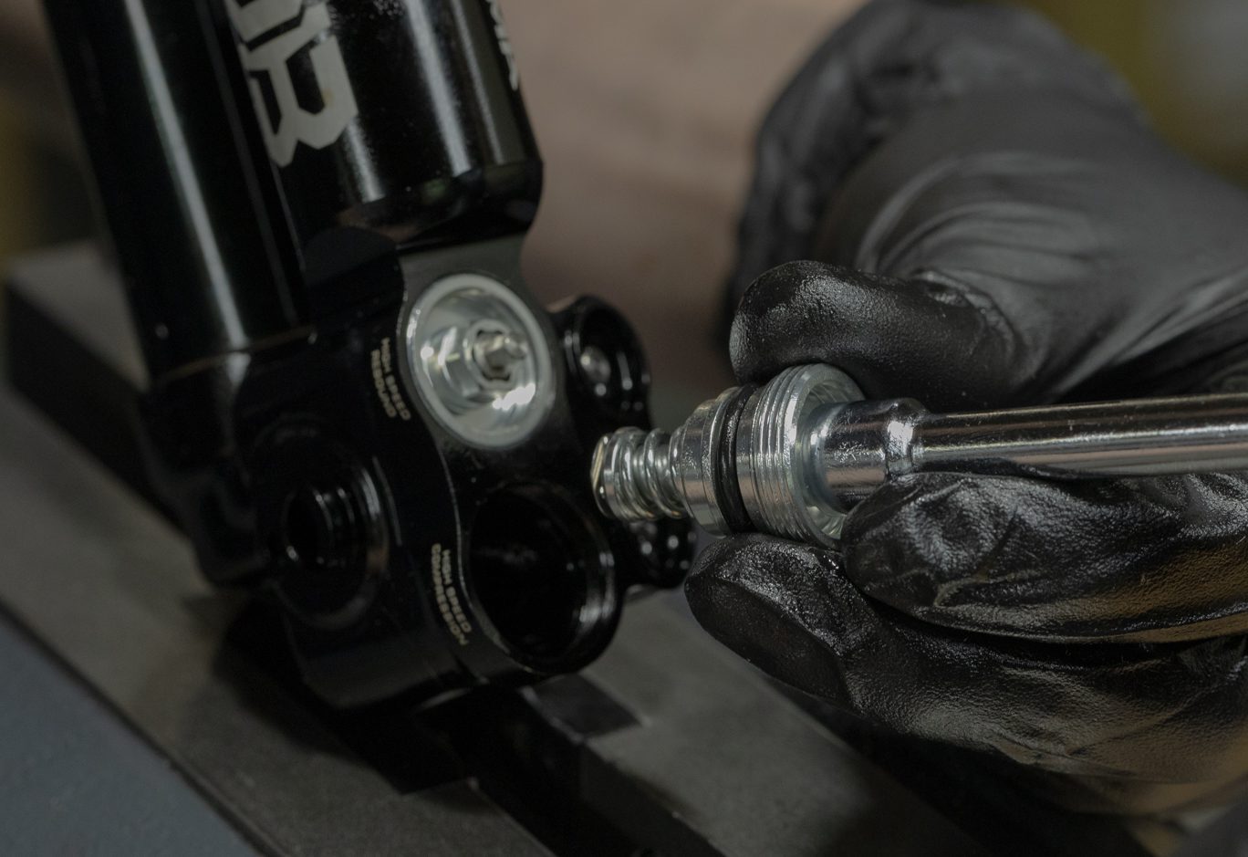
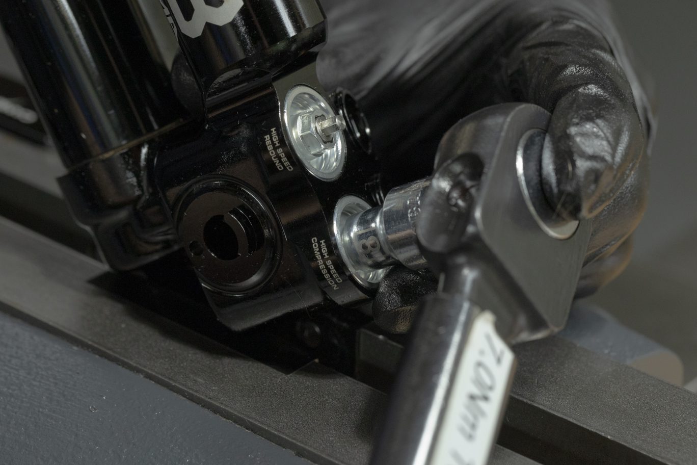
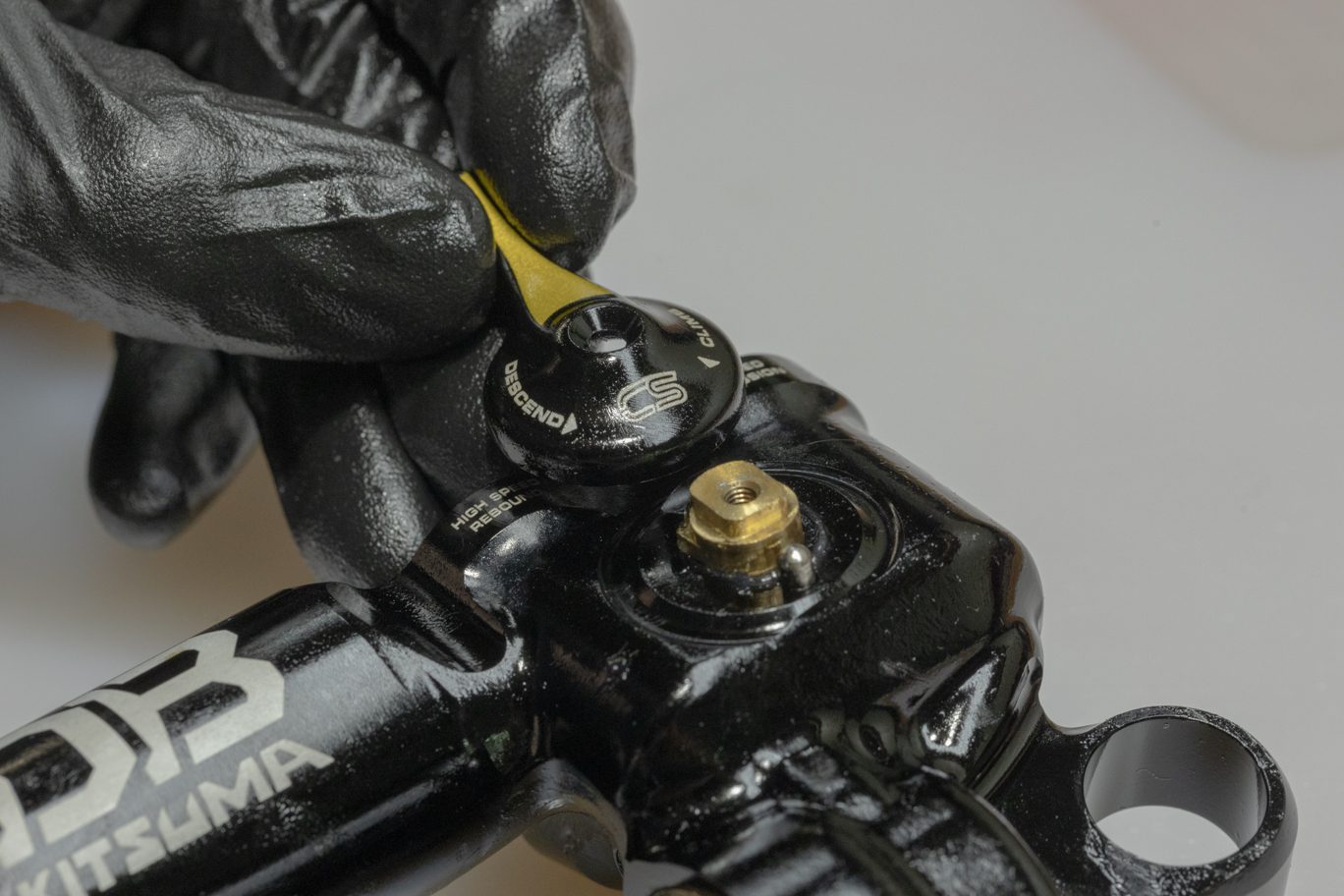
Step 4 – High Speed Adjuster Housing Install
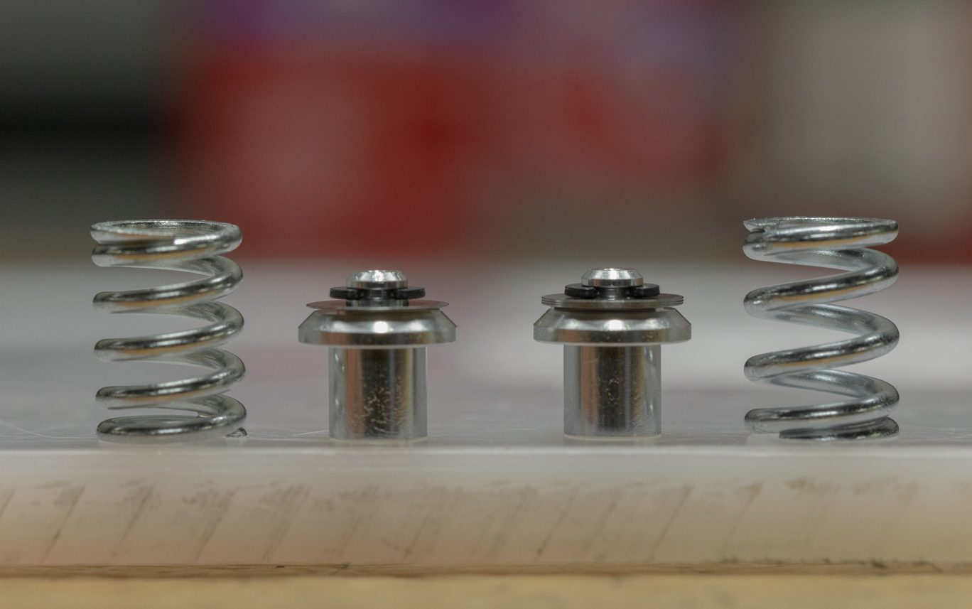
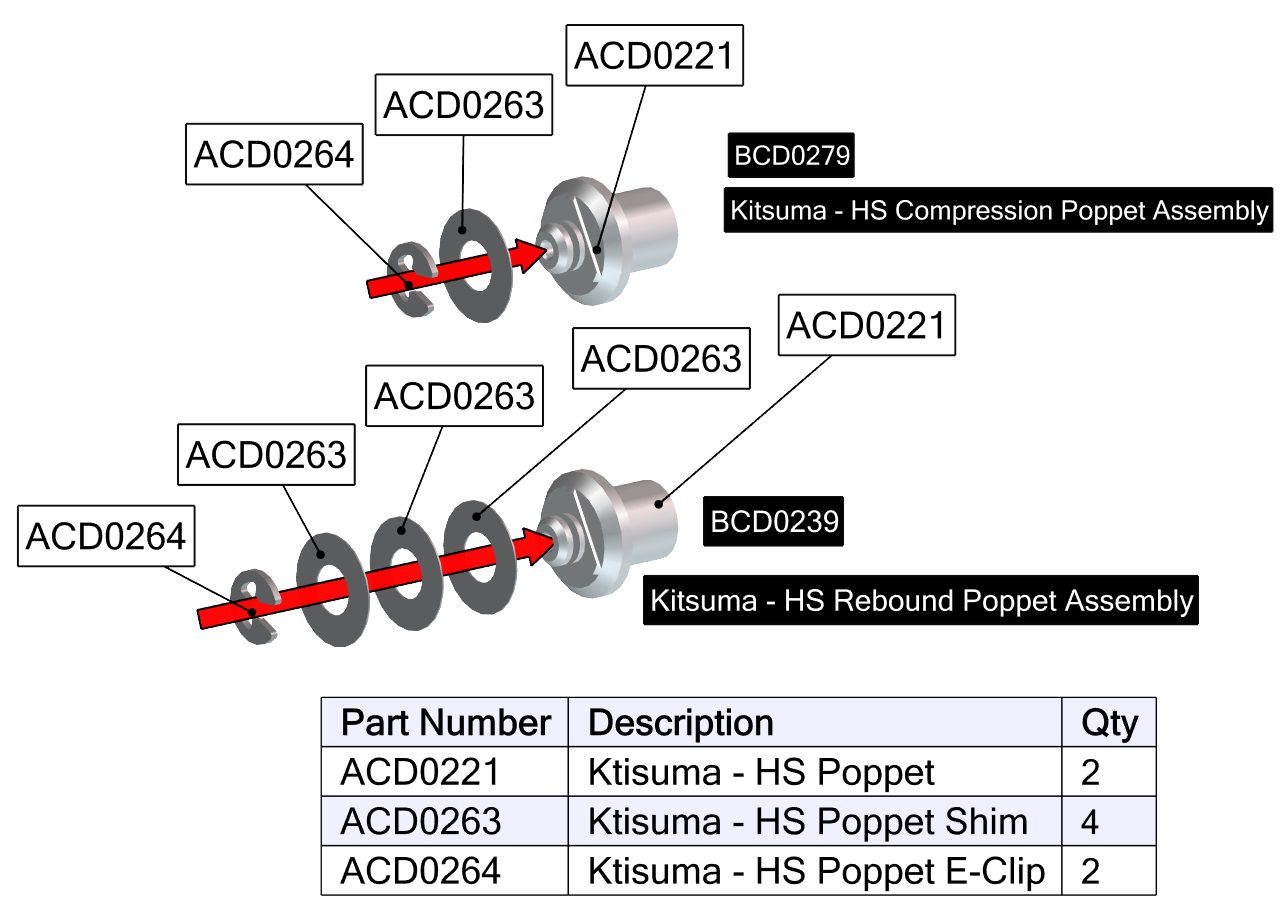
Install poppet assembly with shims towards valve body followed by poppet spring. Note rebound gets the stronger (40w) poppet spring and has 3 shims on poppet; compression has lighter (20w) spring and 1 shim. Using an 8mm socket, torque to 7 Nm.
TSB039 – Kitsuma High Speed Cap (ACD0275) Loctite Removal from Installation
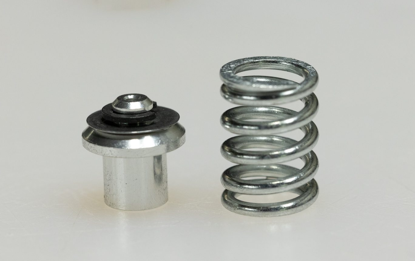
Rebound Spring & Poppet
Compression Spring & Poppet
Compression & Rebound Spring & Poppet
Exploded High Speed Poppets
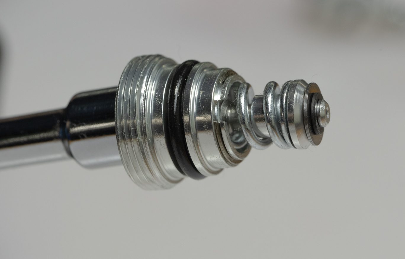
Rebound Spring & Poppet on Adjuster
Rebound Adjuster Assembly Install 1
Rebound Adjuster Assembly Install 2
Rebound Adjuster Assembly Install 3
Compression Spring & Poppet on Adjuster
Compression Adjuster Assembly Install 1
Compression Adjuster Assembly Install 2

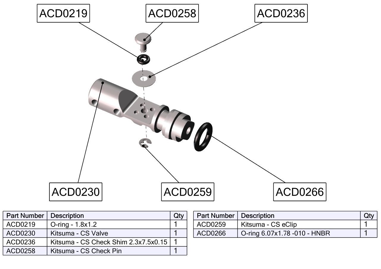
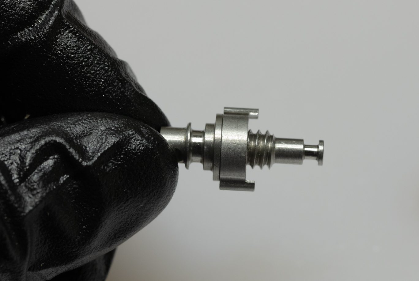
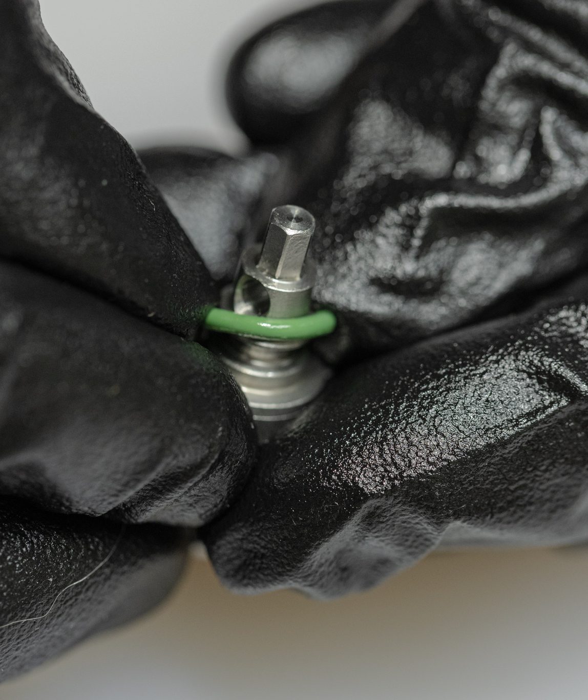
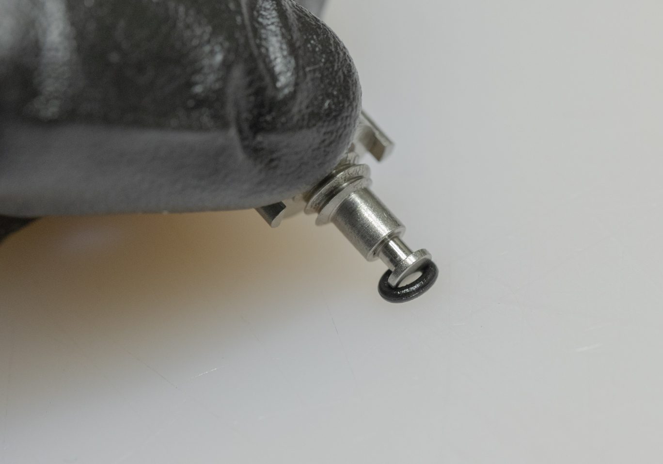
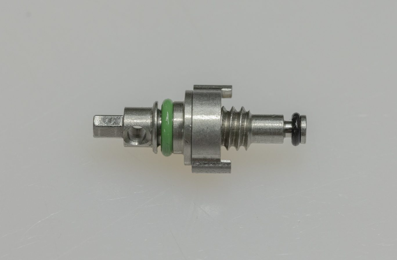
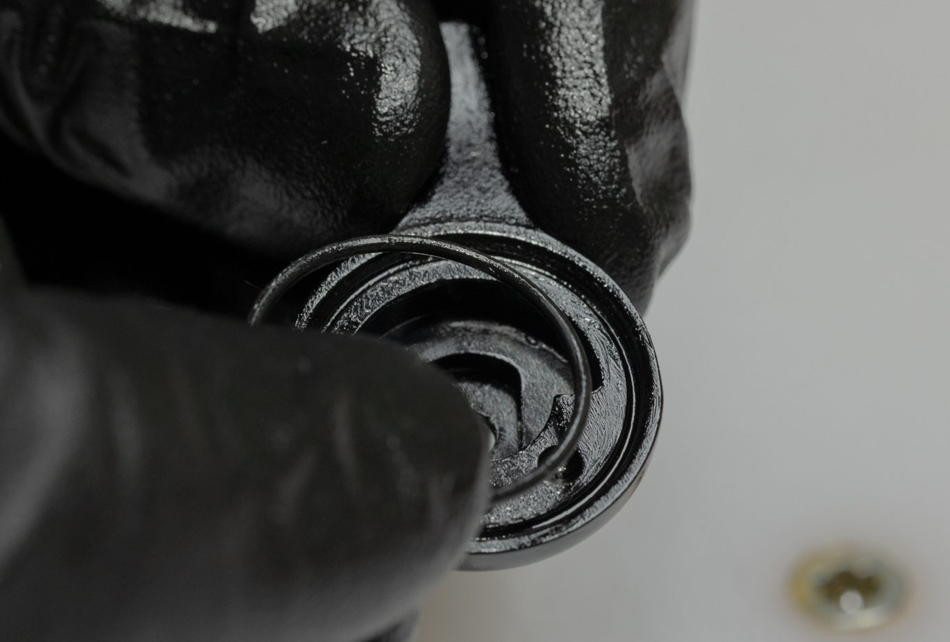
Step 5 – Climb Switch Spool Valve Install
Light grease and install Climb Switch valve o-ring (ACD0266). IL CS bullet (AAD1454) can be used here. Apply grease to Climb Switch valve on valve body and to Climb Switch valve. Insert valve into valve body with tab at 3:00. Once engaged, rotate CS valve tab underneath valve body tab.
CS Spool Valve O-Ring Install 1
CS Spool Valve O-Ring Install 2
CS Spool Valve O-Ring Installed
Exploded Climb Switch Spool Valve
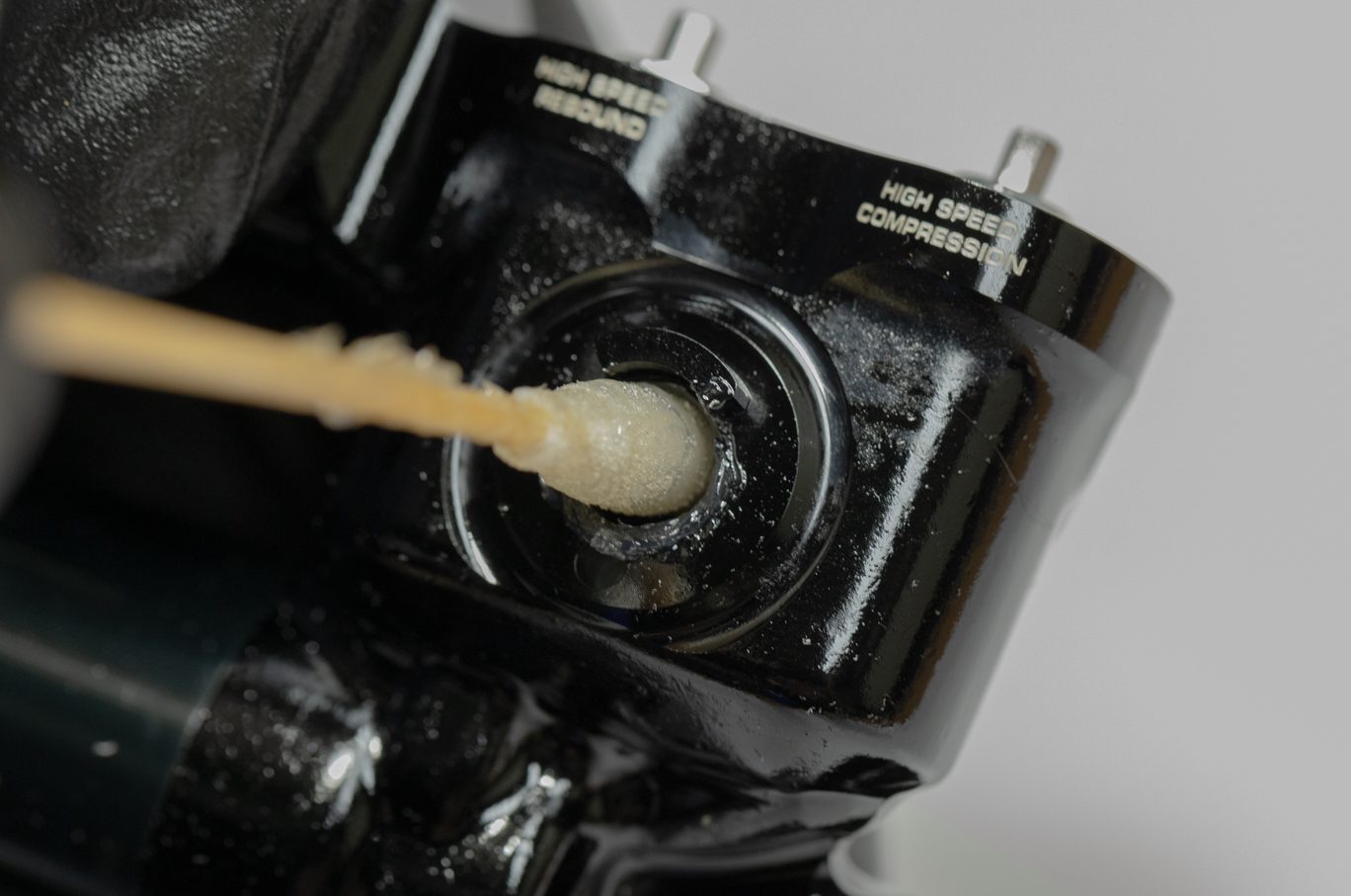
Greasing Valve Body
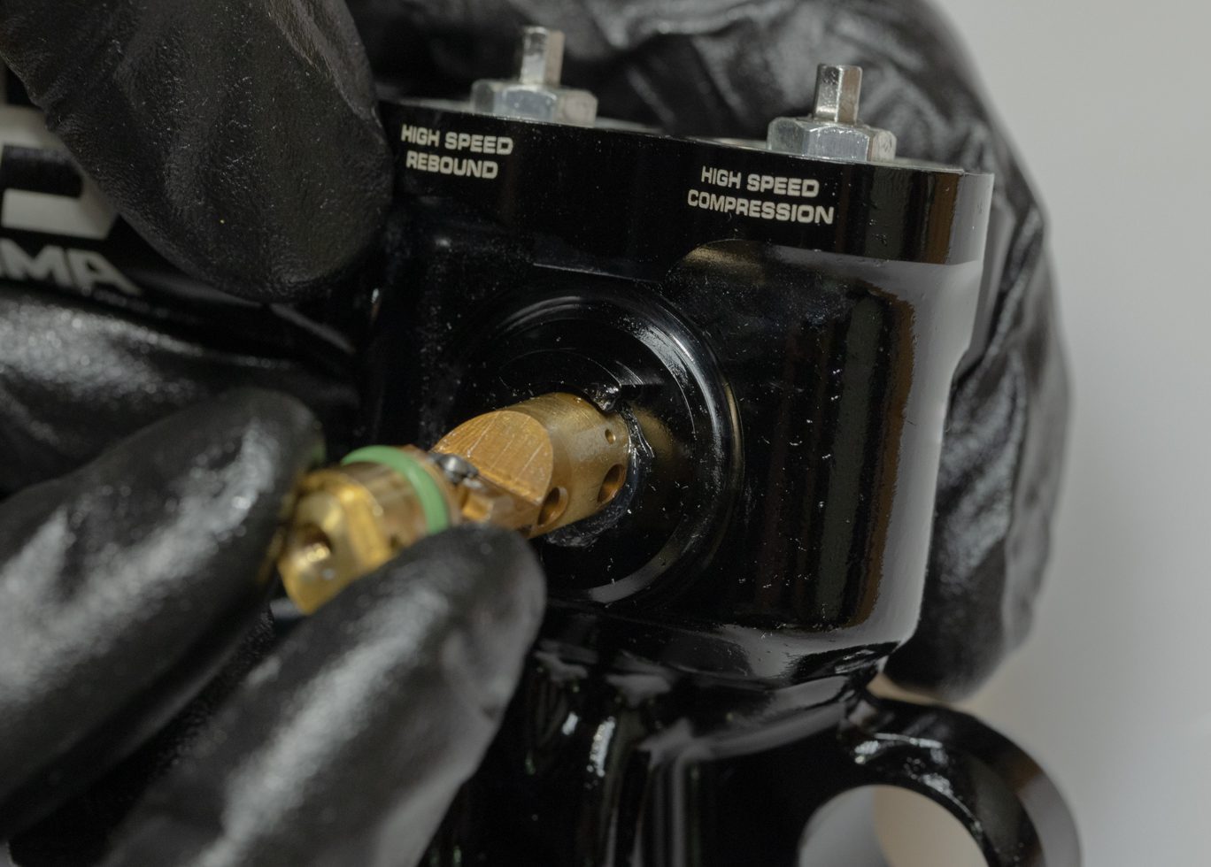
CS Spool Valve Install
CS Spool Valve Clocking
CS Spool Valve Properly Clocked
Climb Switch Detent Install
Climb Switch Detent Installed
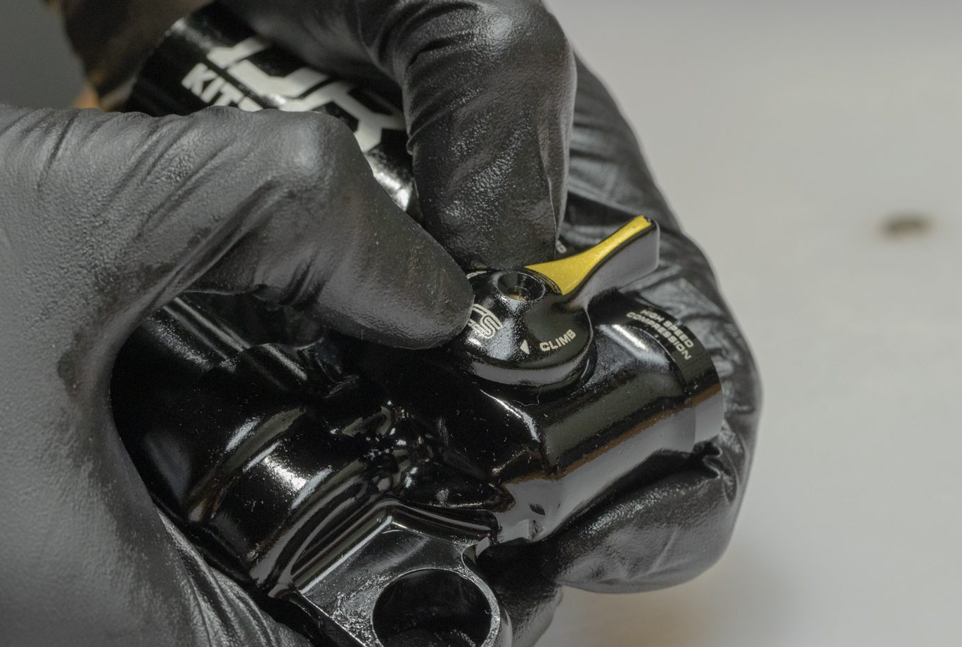
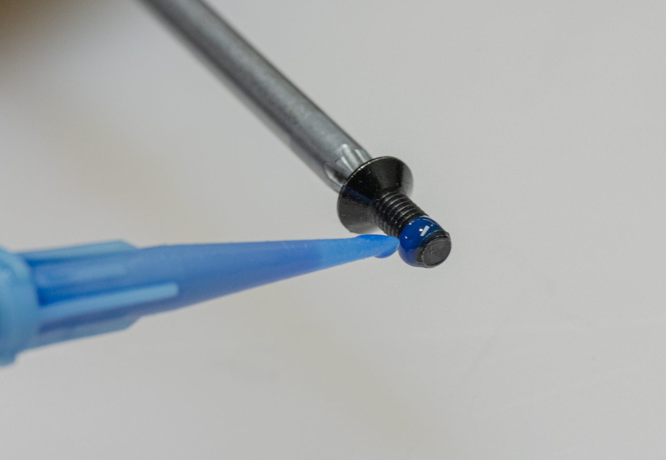
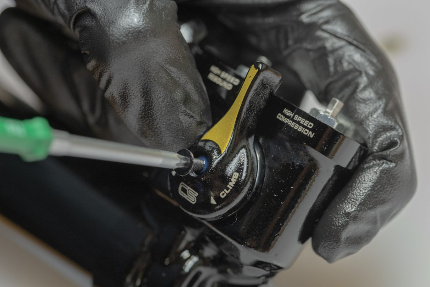
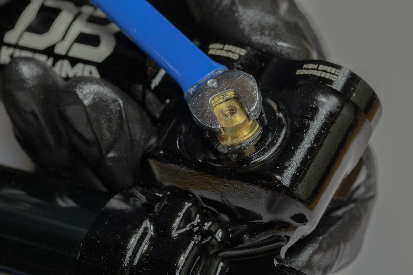
Step 6 – Climb Switch Lever Install
Light grease and install Climb Switch o-ring (AAD0800) on back side of lever. Place lever onto Climb Switch valve with lever at 9:00. Note that proper orientation of lever and valve required for proper interface. Apply blue Loctite (243) to Climb Switch mounting bolt. Secure CS lever with bolt. Torque to 1.2 Nm with T10.
Climb Switch O-Ring Install
Climb Switch O-Ring Installed
Climb Switch Proper Alignment
Climb Switch Installed
Climb Switch Mount Screw Prep
Climb Switch Mount Screw Install
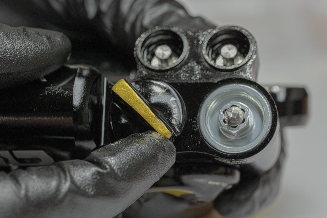
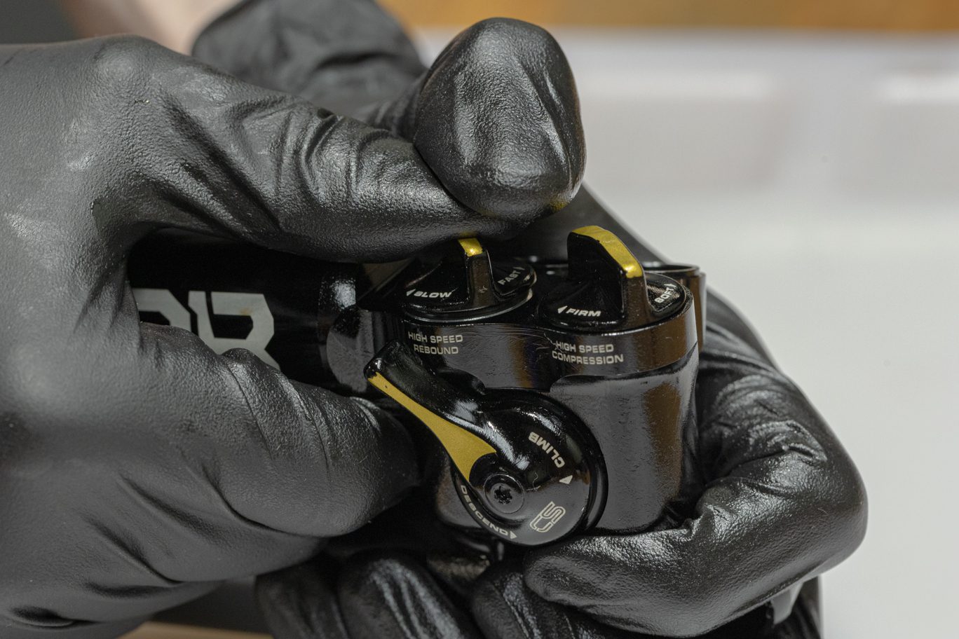
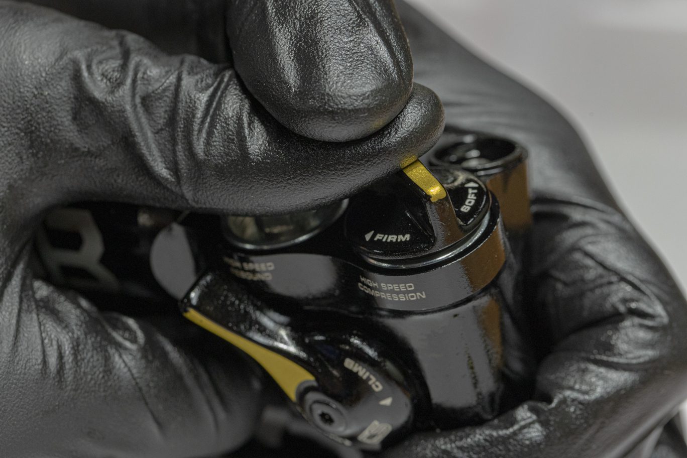
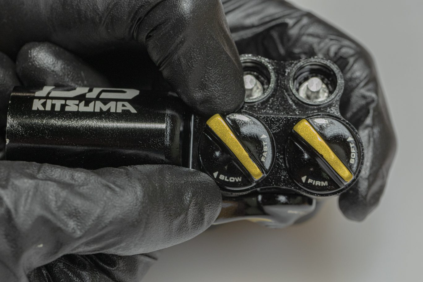
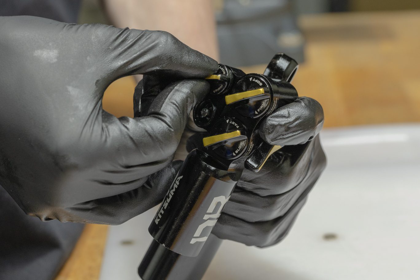
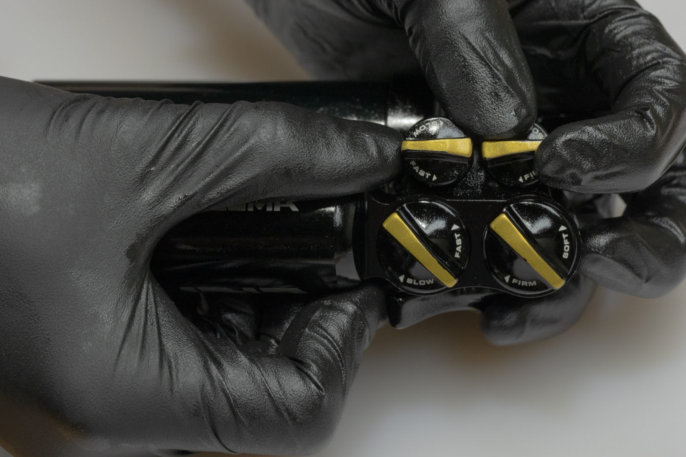
Step 7 – High Speed Dials Install
Lightly grease and install high speed adjustor dial o-rings (ACD0276) on back of dial. Fully open (counterclockwise) high speed controls and install dial with indicator in the 1:00 to 3:00 range as allowed by the interface.
High Speed Dial O-Ring Install
High Speed Rebound Dial Install
High Speed Compression Dial Install
High Speed Rebound Dial Seating
High Speed Compression Dial Seating
High Speed Dials Installed
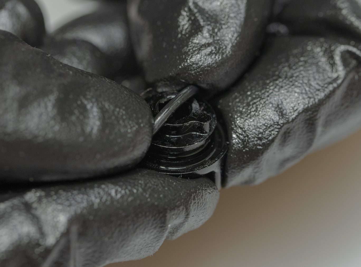
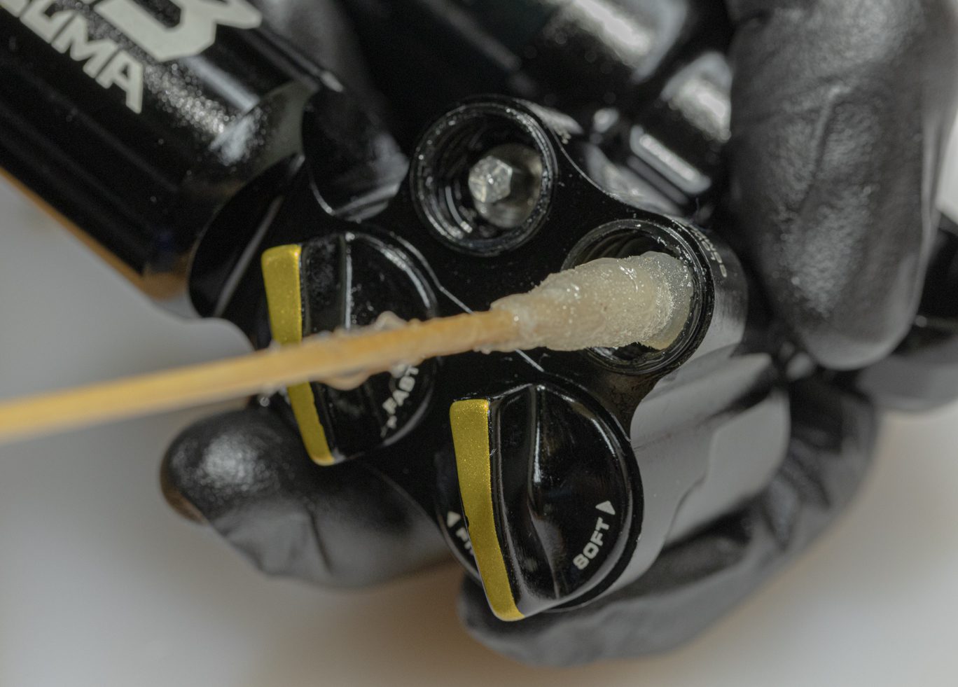
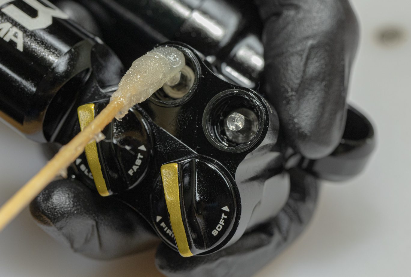
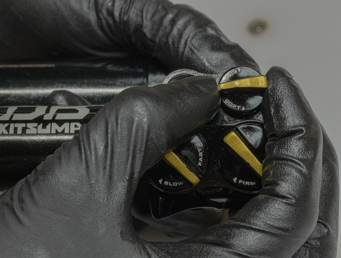
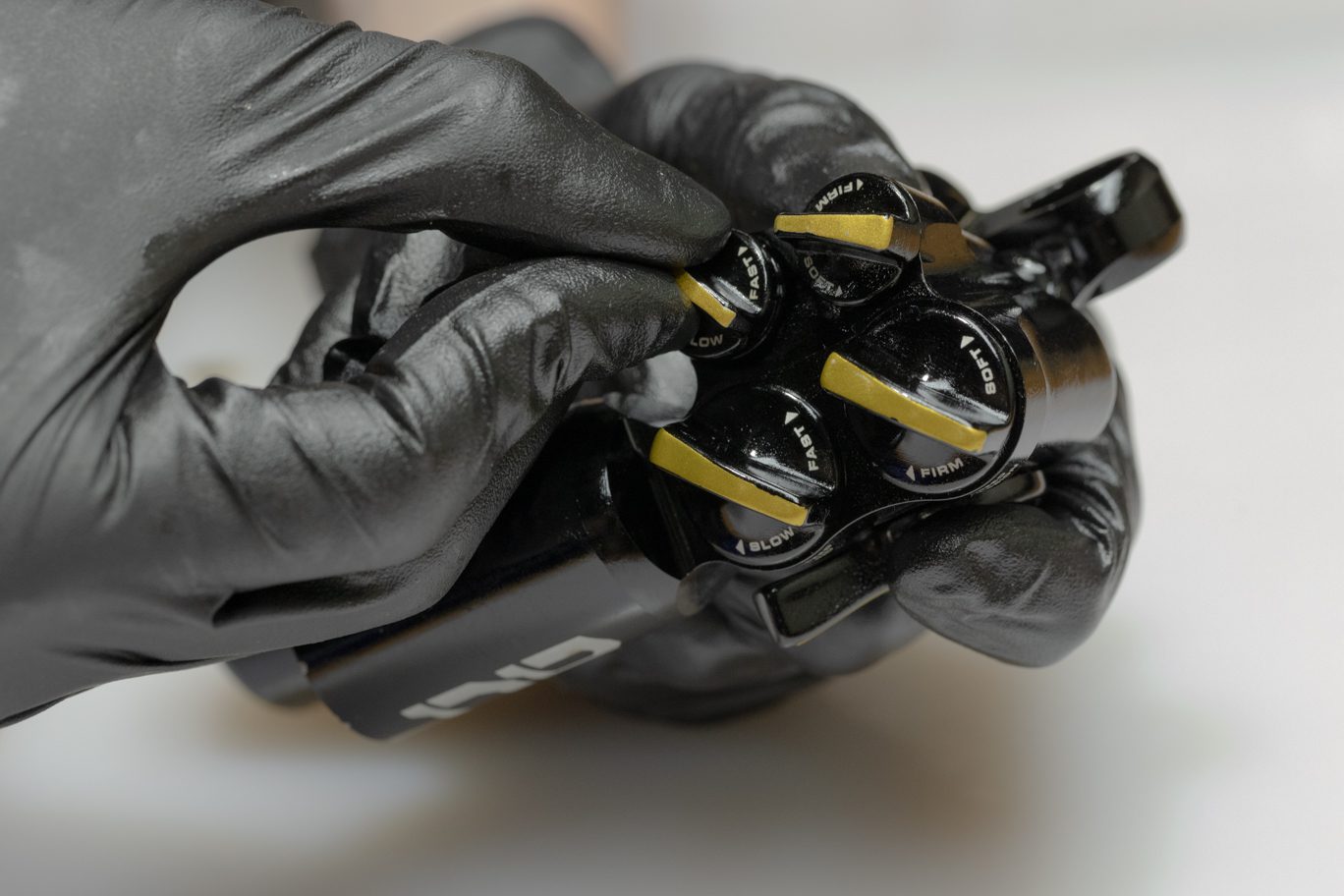
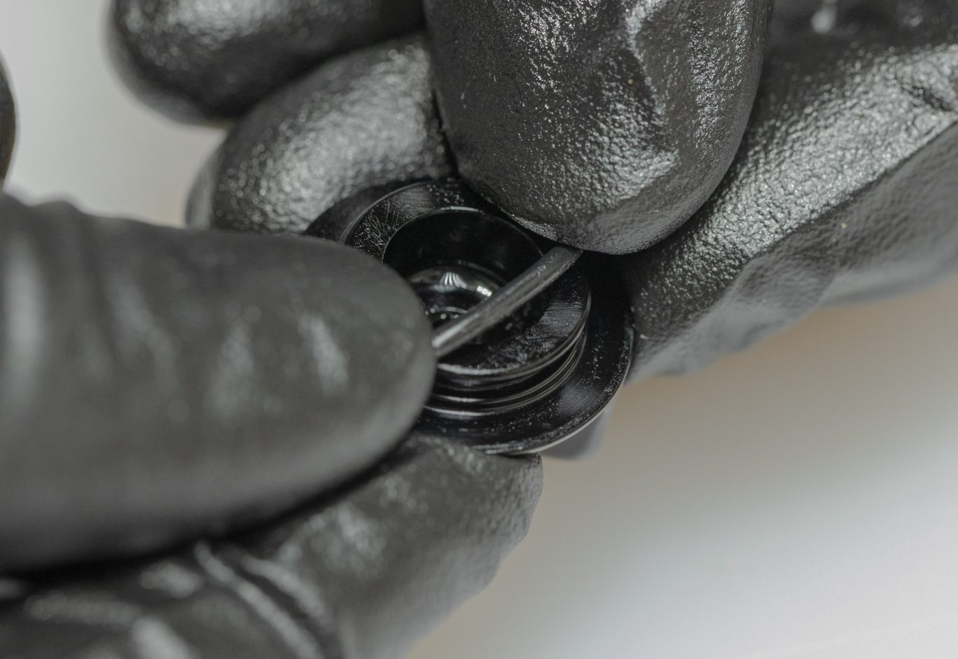
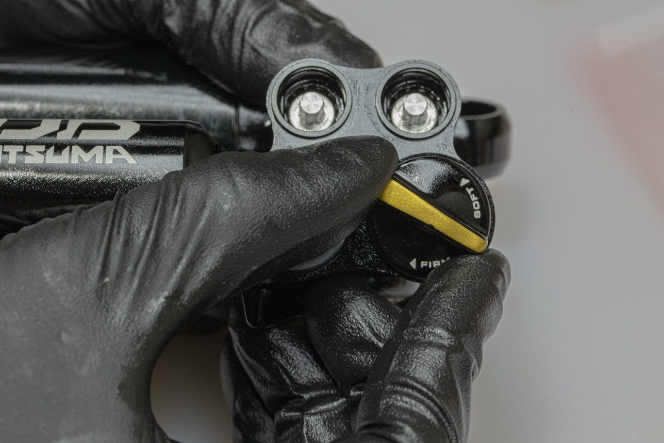
Step 8 – Low Speed Dials Install
Lightly grease and install low speed adjustor dial o-rings (ACD0254) on back of dial. Apply thin layer of grease to the valve/dial interface on the valve body. Check that low speed controls are fully closed (clockwise). Line up dial at 6:00. Rotate dial and valve counterclockwise while applying gentle pressure until the dial seats onto the valve.
Low Speed Dial O-Ring Install
Greasing Low Speed Compression Valve Body
Greasing Low Speed Rebound Valve Body
Low Speed Compression Dial Install
Low Speed Compression Dial Rotation
Starting with Low Speed at 6:00
Low Speed Rebound Dial Rotation
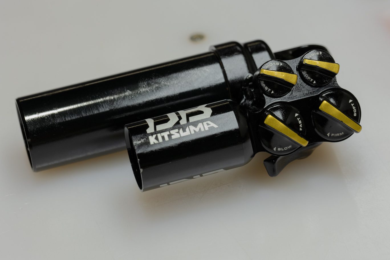
All Dials Installed
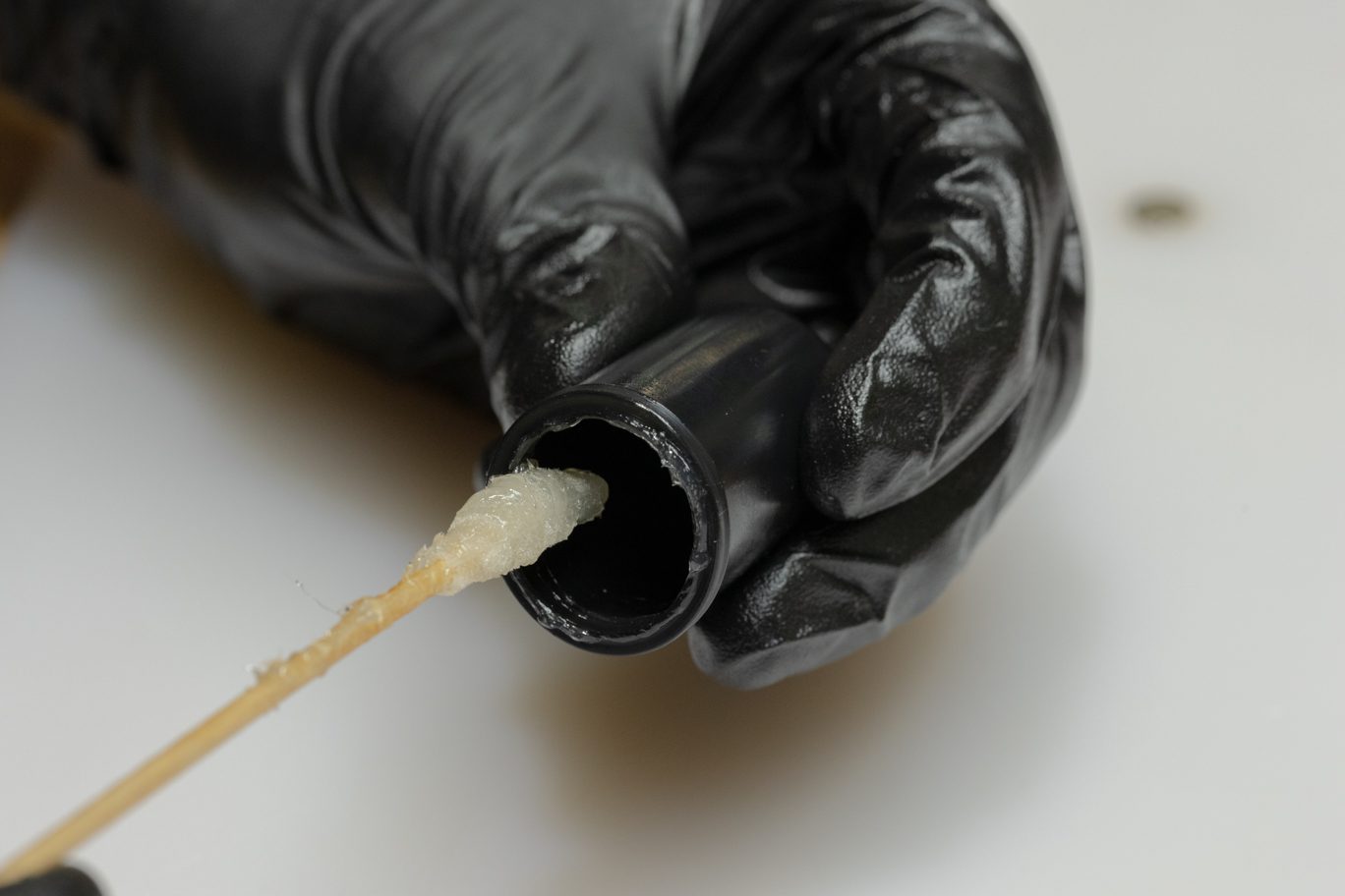

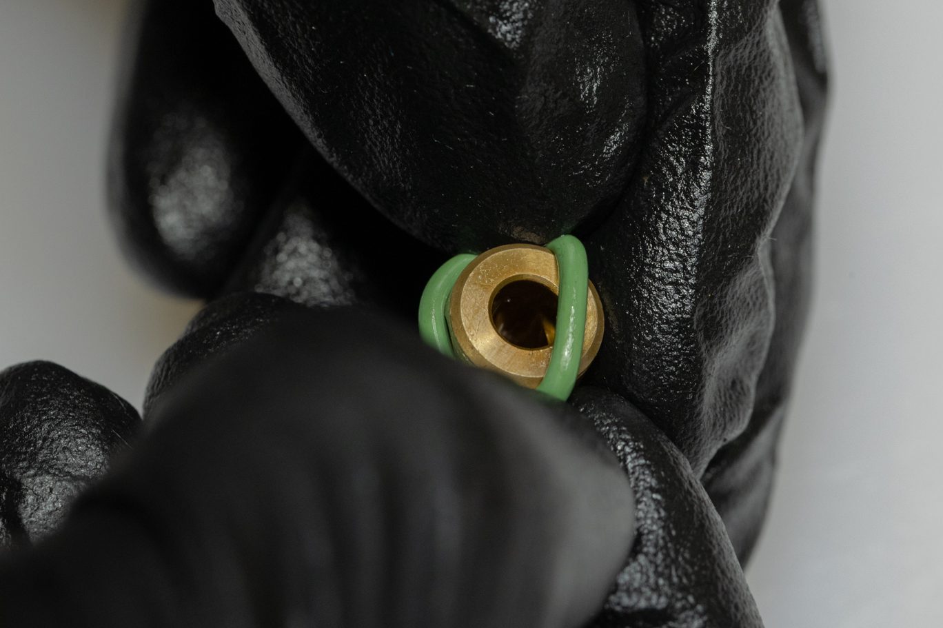
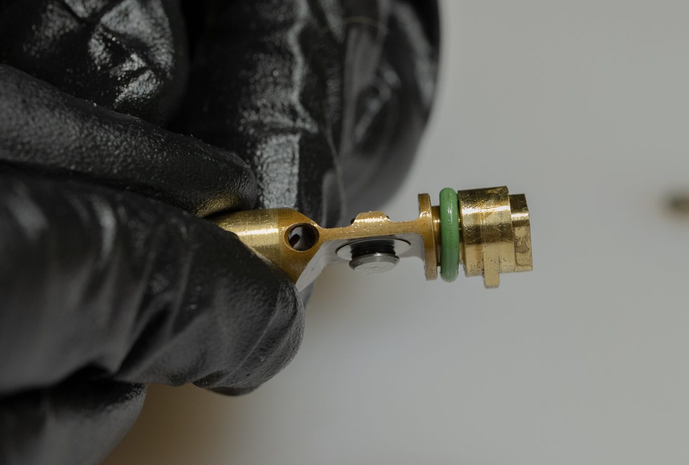
Step 9 – Reservoir Bladder & End Cap Install
If updating from older IFP system, a new reservoir end cap (BCD0169) is required.
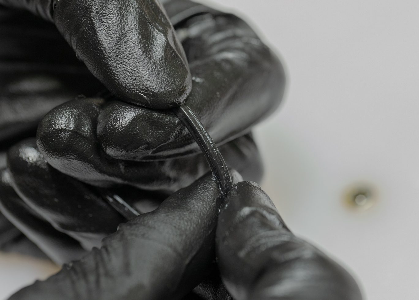
Grease all three sides of the quad ring portion of bladder.
Work bladder onto reservoir cap. Insert end cap/bladder assembly into reservoir. Apply pressure to fully seat and expose circlip channel. Install circlip. Back end cap out against circlip using bladder fill tool or IFP setting tool.
TSB045 – Kitsuma IFP Changed to Bladder
Greasing Bladder Quad Ring, Side 1
Greasing Bladder Quad Ring, Side 2
Greasing Bladder Quad Ring, Side 3
Installing Bladder on Res End
Bladder & Res End Assembly Install 1
Bladder & Res End Assembly Install 2
Seating Bladder & Res End
Installing Res End Circlip
Res End Circlip Installed
Backing Res End Against Circlip
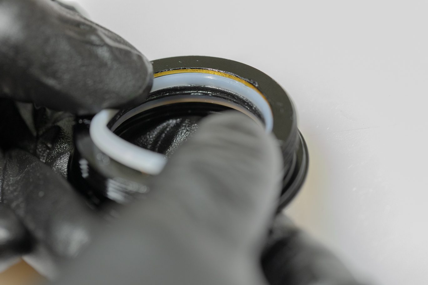
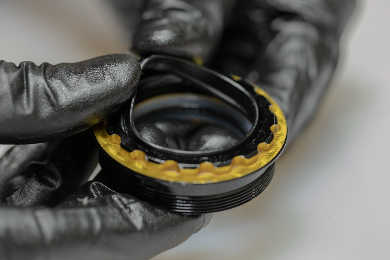
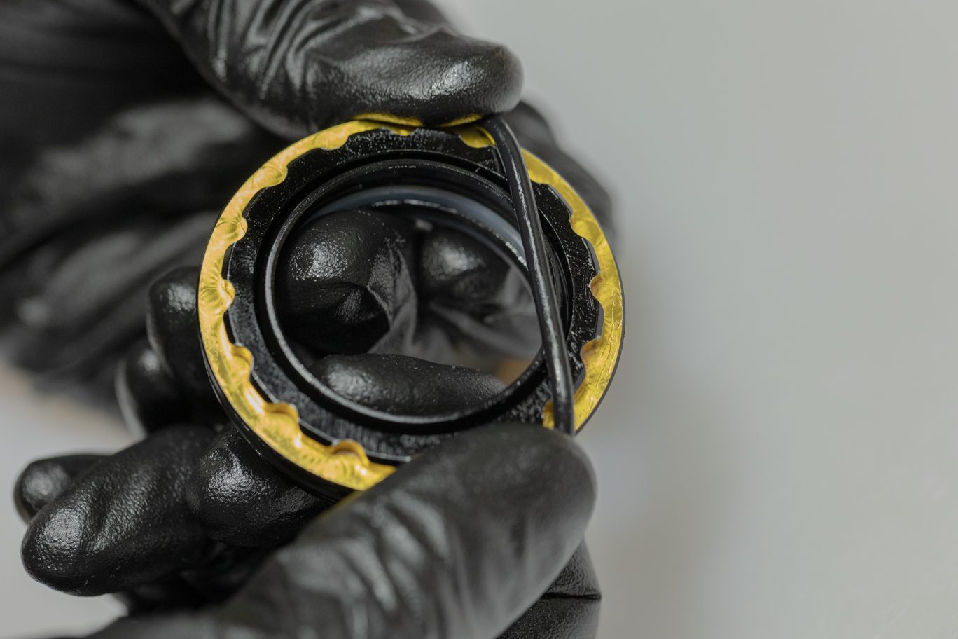
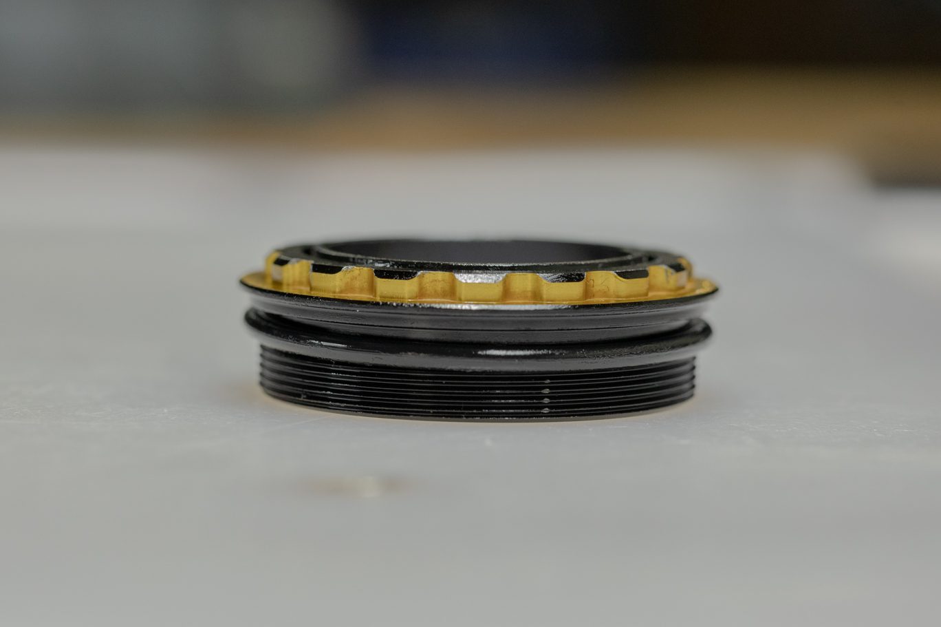
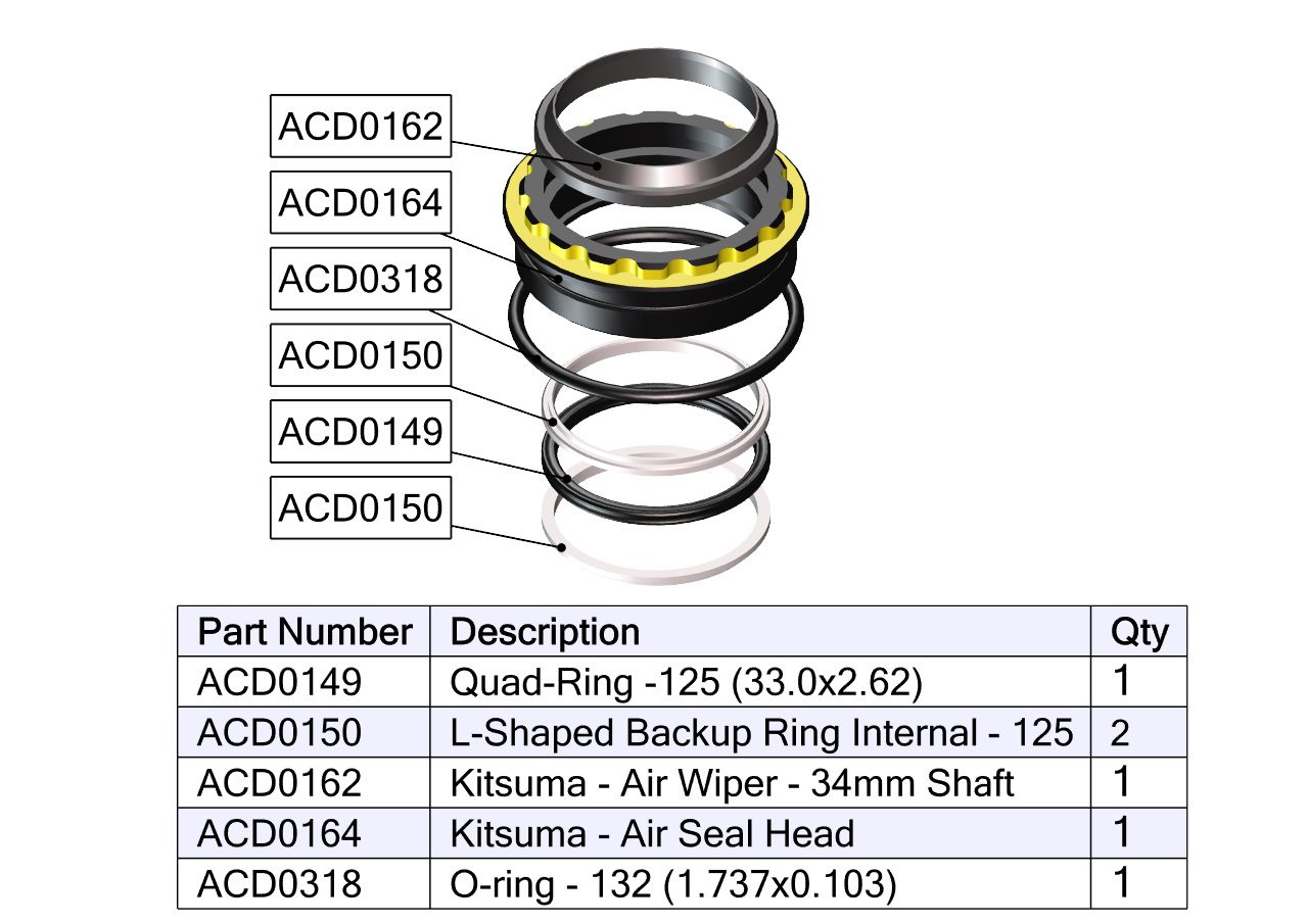
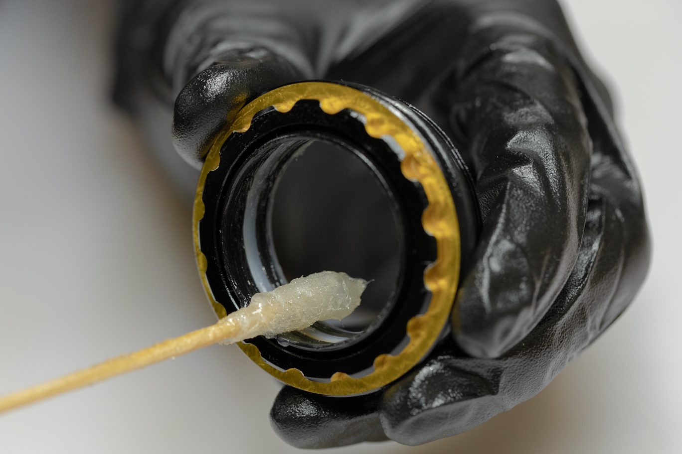
Step 10 – Air Seal Head Reassembly
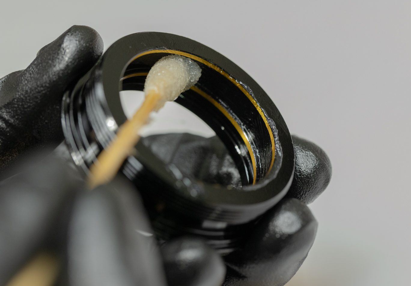
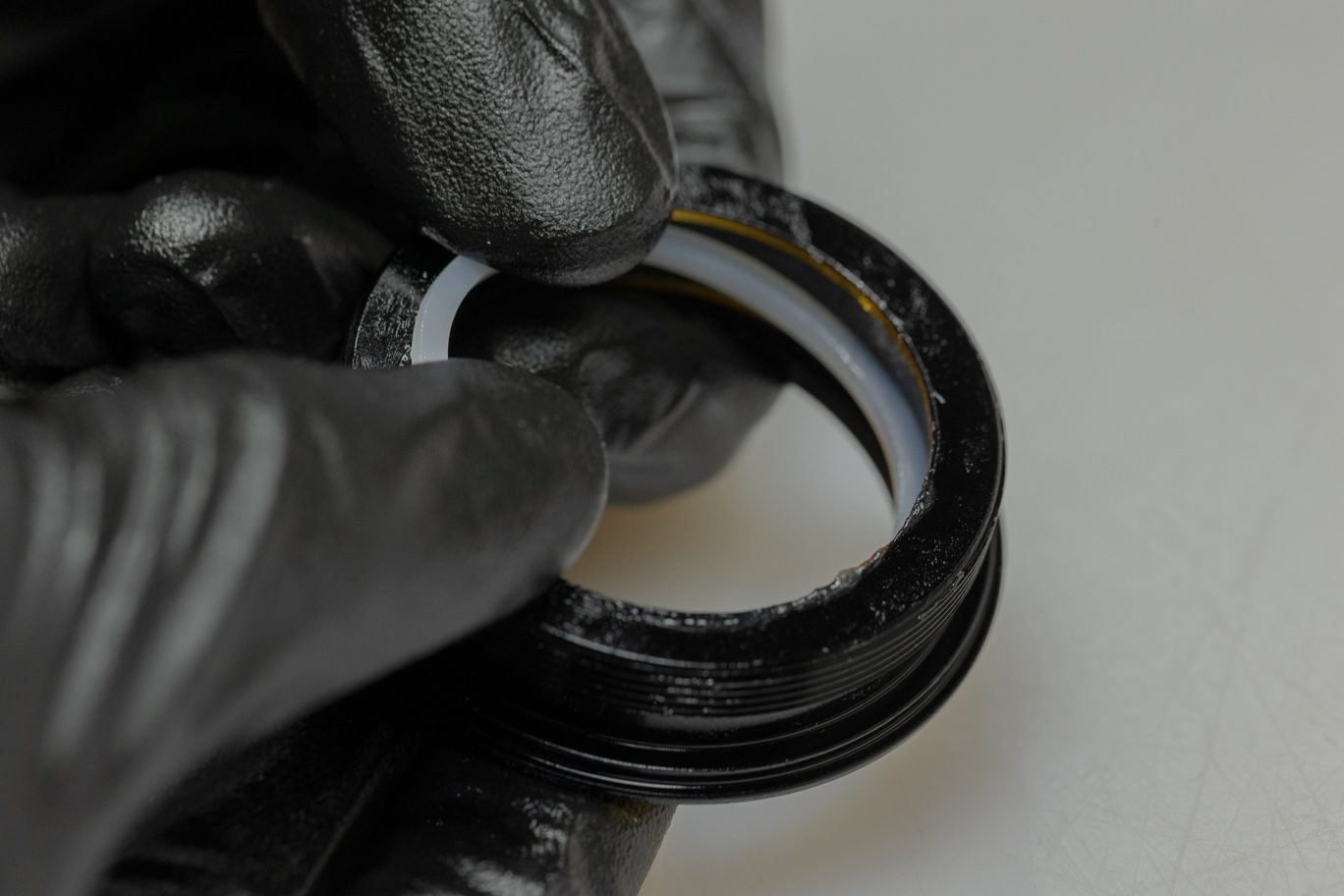
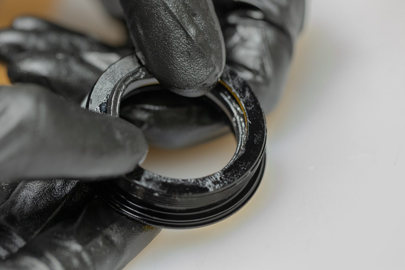
Thoroughly grease new air seal head quad ring (ACD0149) and quad ring channel on air seal head. Install new L-ring (ACD0150), quad ring and second L-ring with flat sides of L-rings towards quad ring. Install new dry wiper seal (ACD0162) into air seal head. Lightly grease and install new air seal head o-ring (ACD0318) on outside of air seal head.
Air Seal Head Quad Ring Greasing
Air Seal Head Quad Ring Channel Greasing
Air Seal Head First L-Ring Install
Air Seal Head Quad Ring Install
Air Seal Head Second L-Ring Install
Air Seal Head Wiper Seal Install
Air Seal Head O-Ring Install
Complete Air Seal Head
Exploded Air Seal Head Assembly
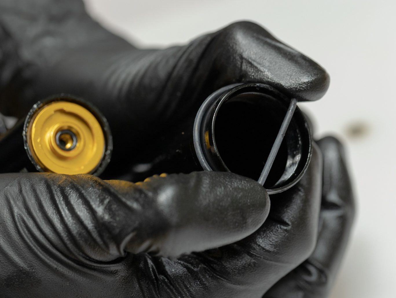
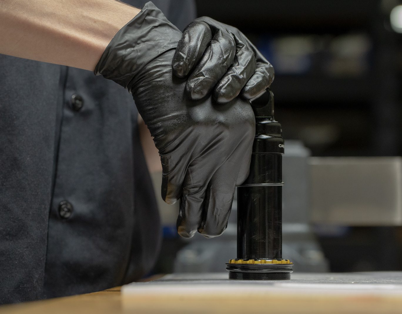
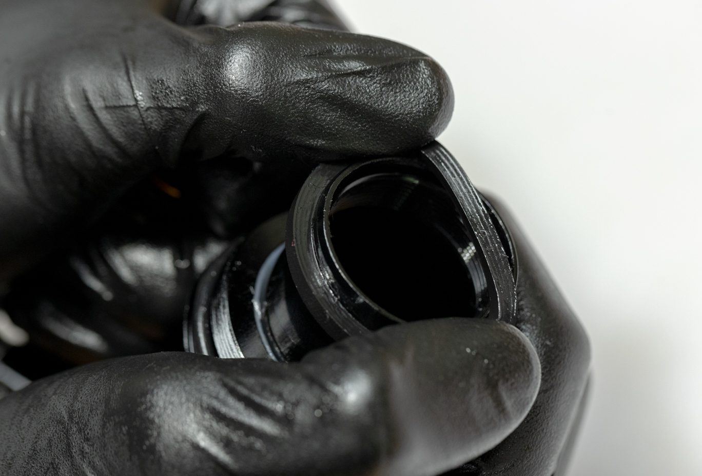
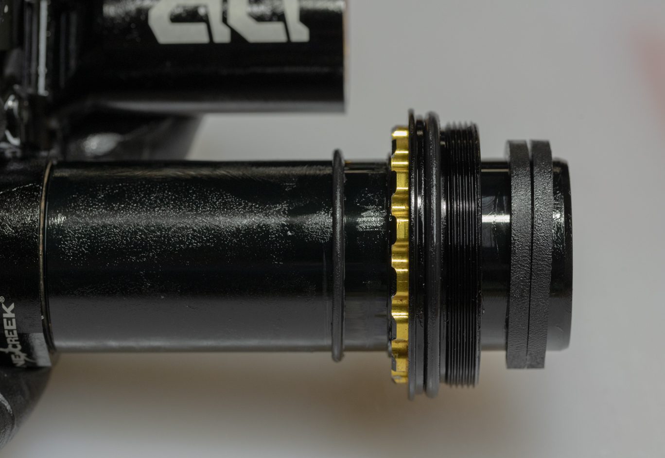
Step 11 – Air Seal Head Install
Apply grease to inside of completed air seal head assembly. Install new sag indicator o-ring (AAD0837) onto outer damper tube. Place air seal head on flat surface. With even pressure, insert damper tube into air seal head. Take care to not rock damper tube while installing to avoid rolling or cutting air seal head quad ring. Reinstall negative volume reduction bands if present.
Air Seal Head Greasing
Sag O-Ring Install
Air Seal Head Install
Negative Volume Bands Install
Sag O-Ring, Air Seal Head, Negative Volume Bands Installed
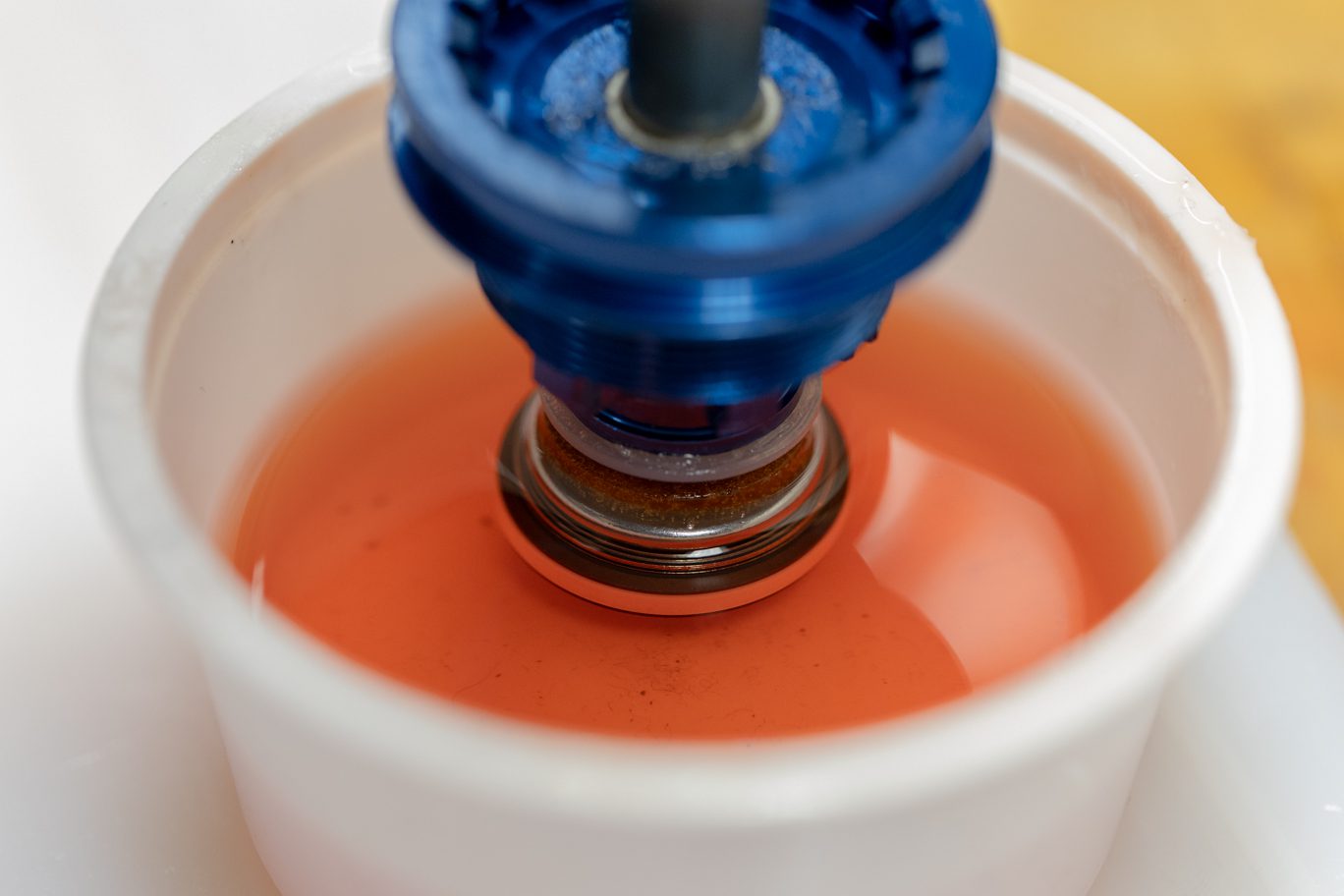
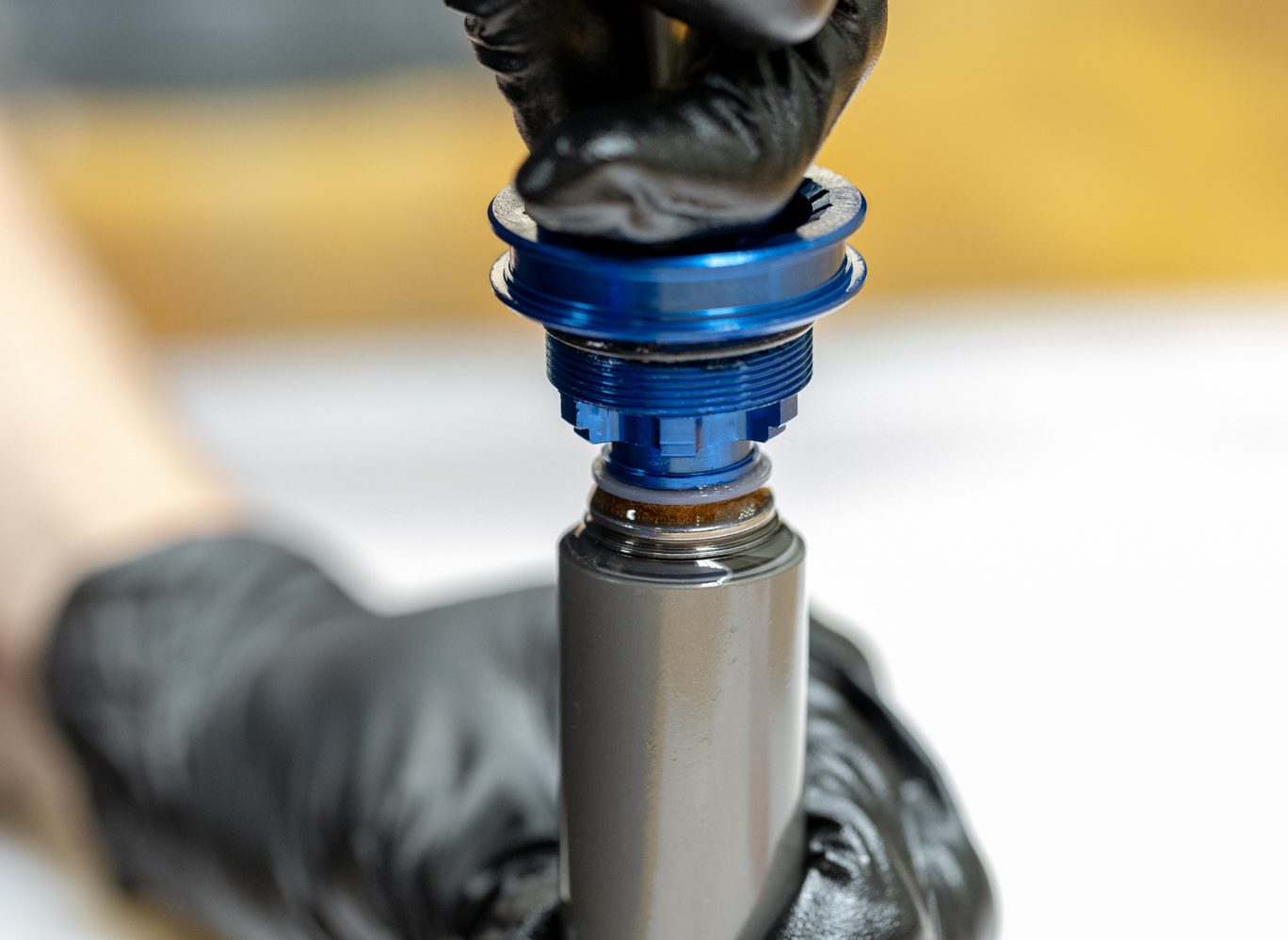
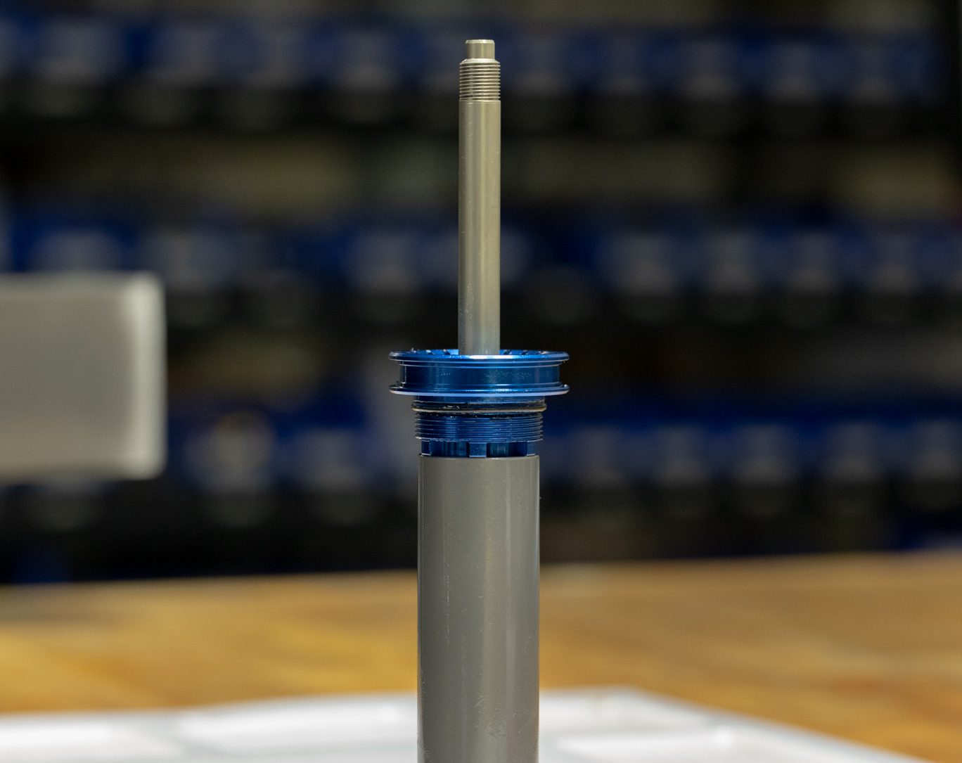
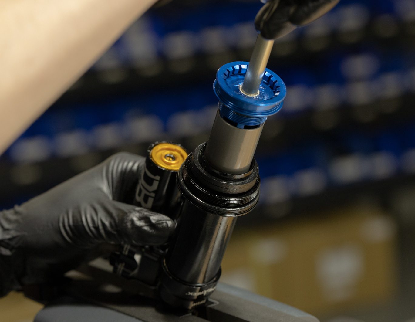
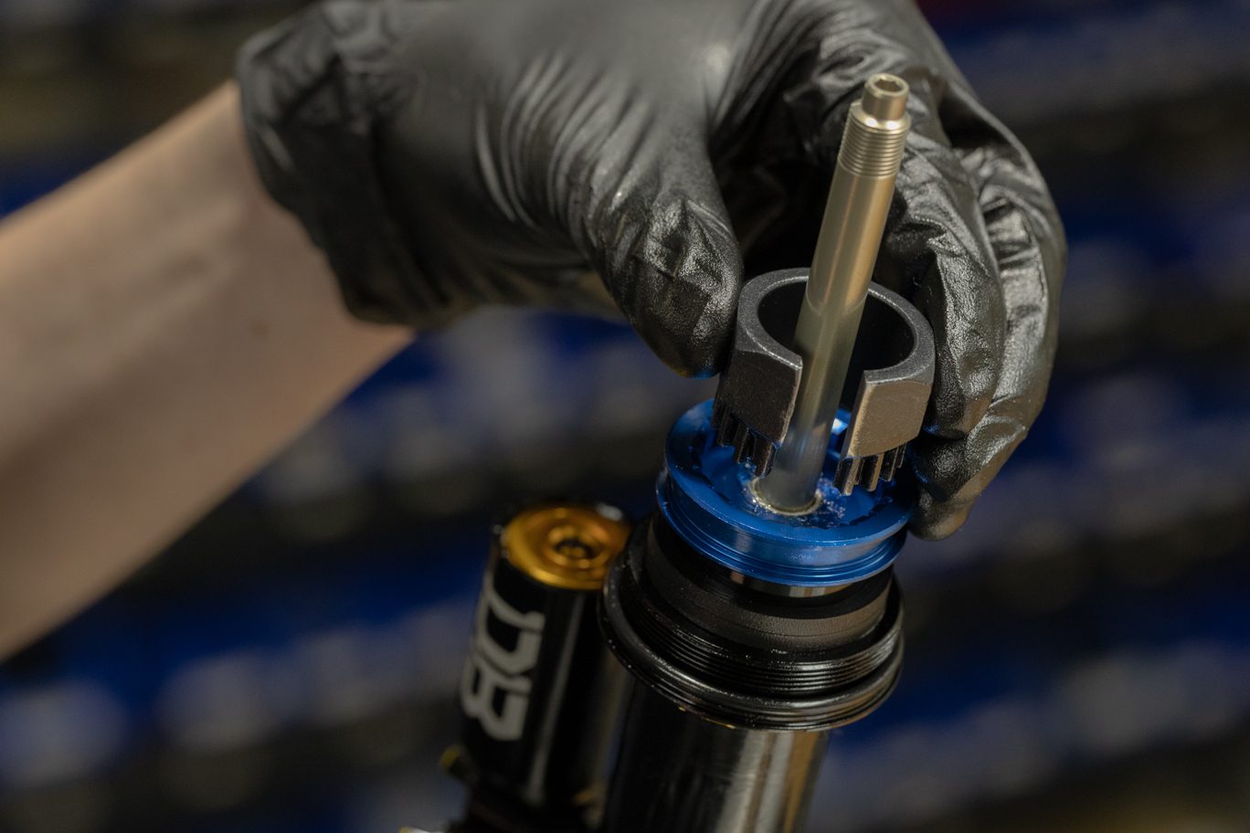
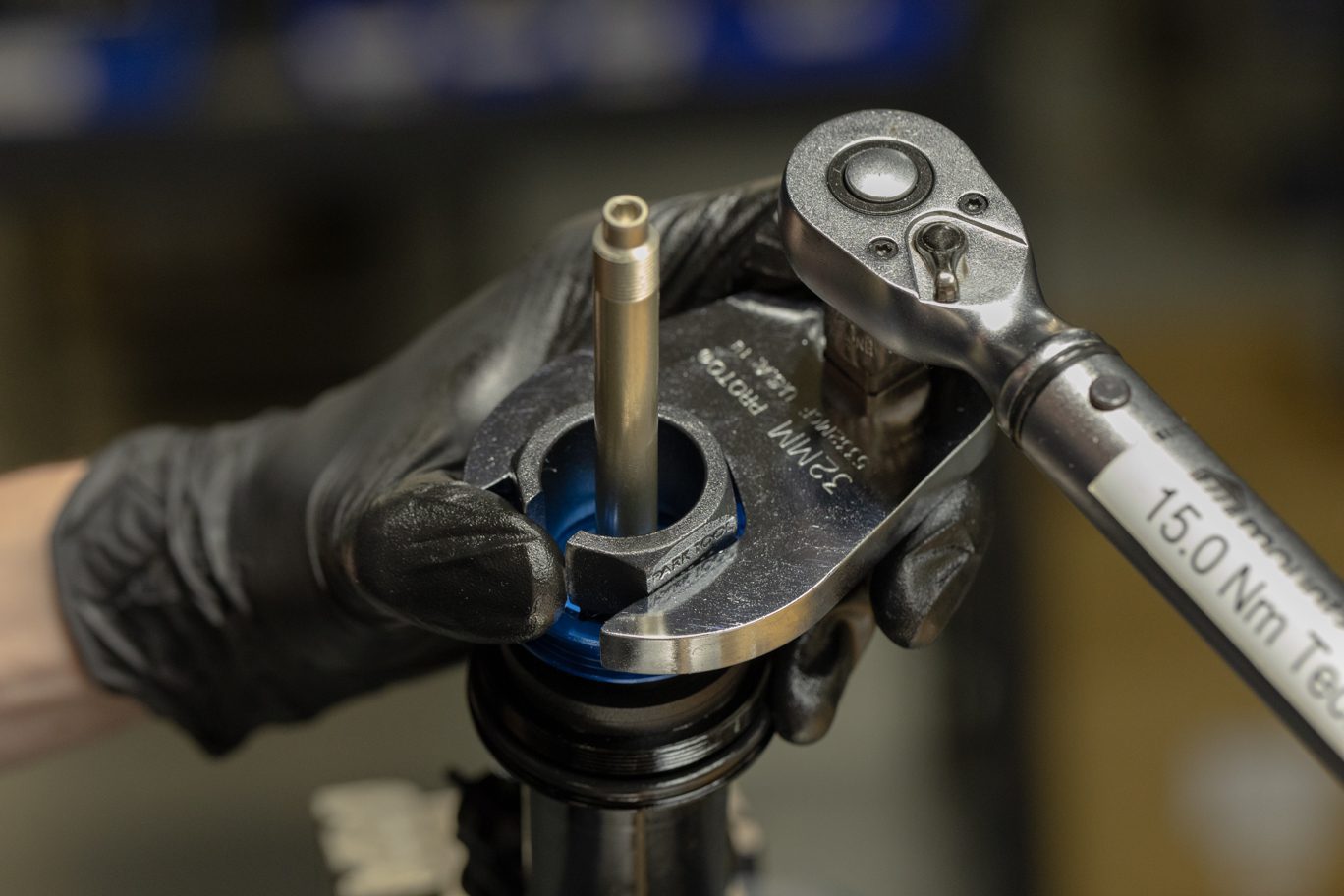
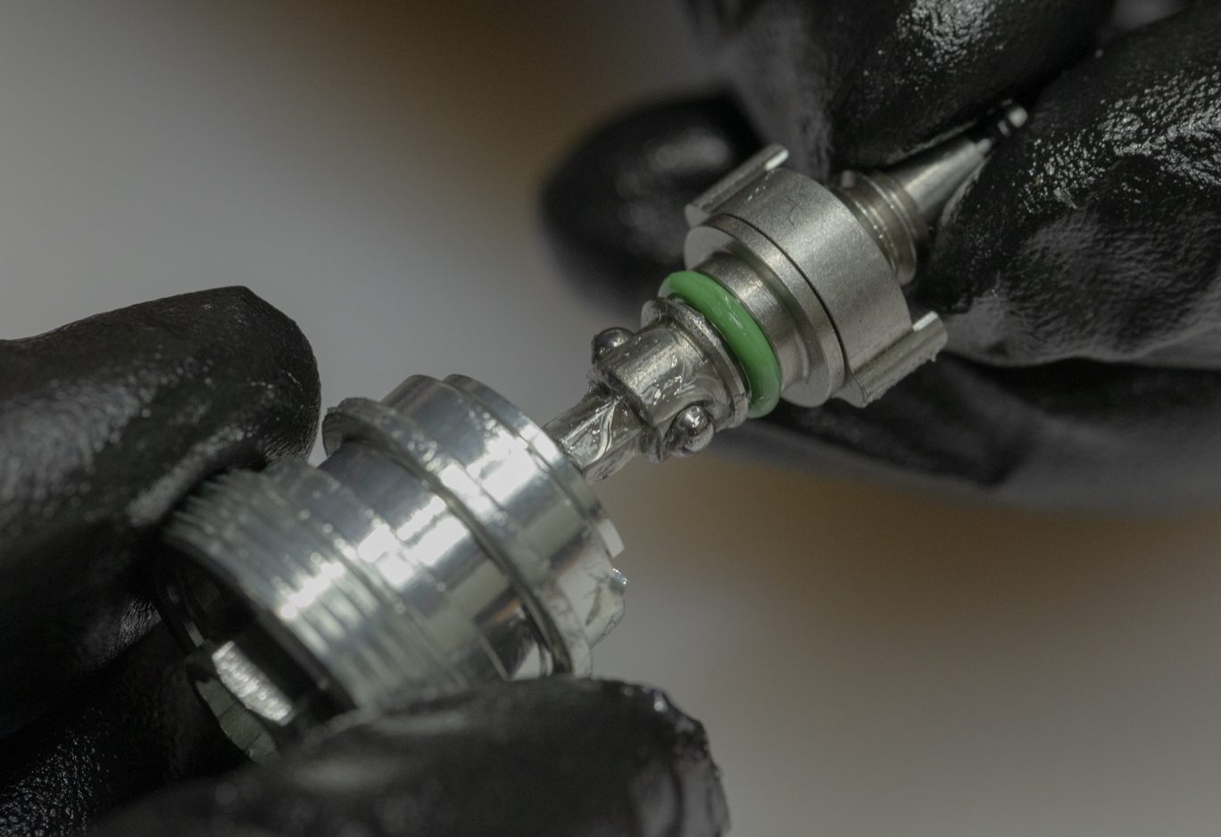
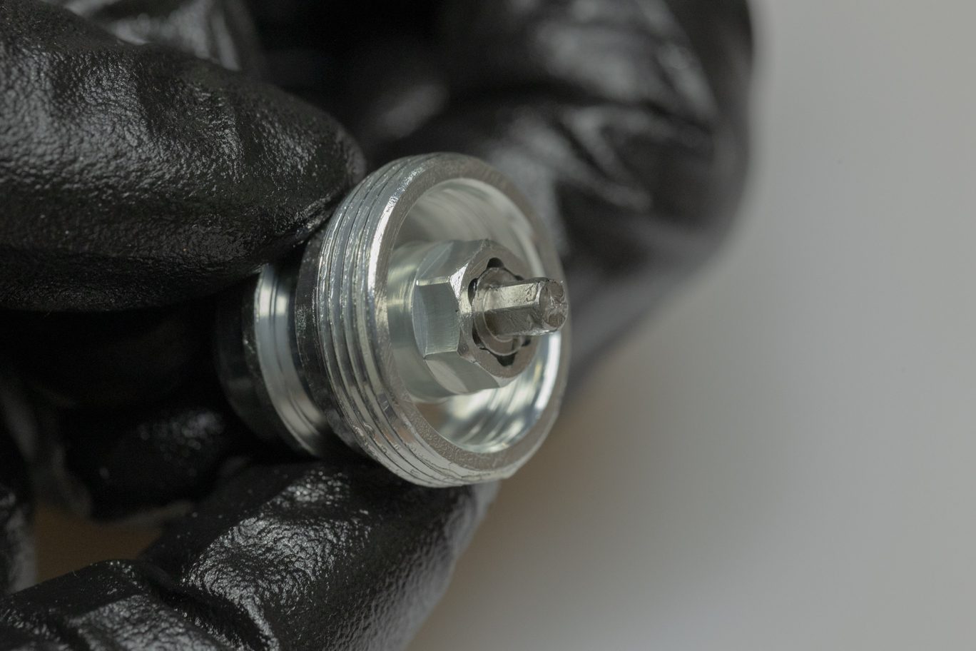
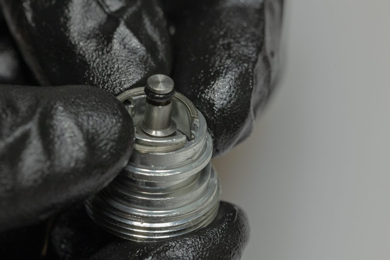
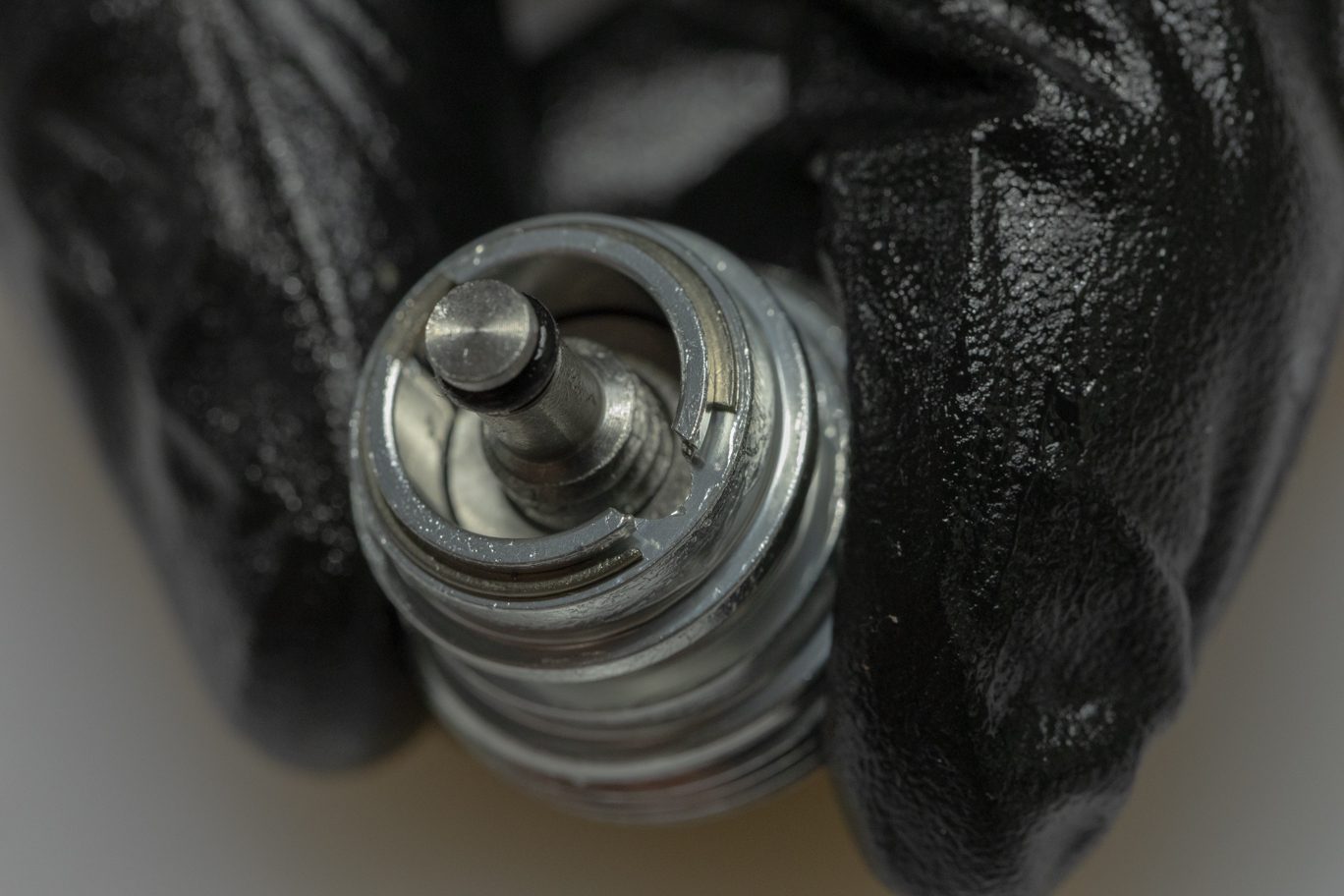
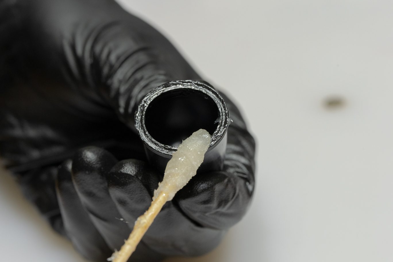
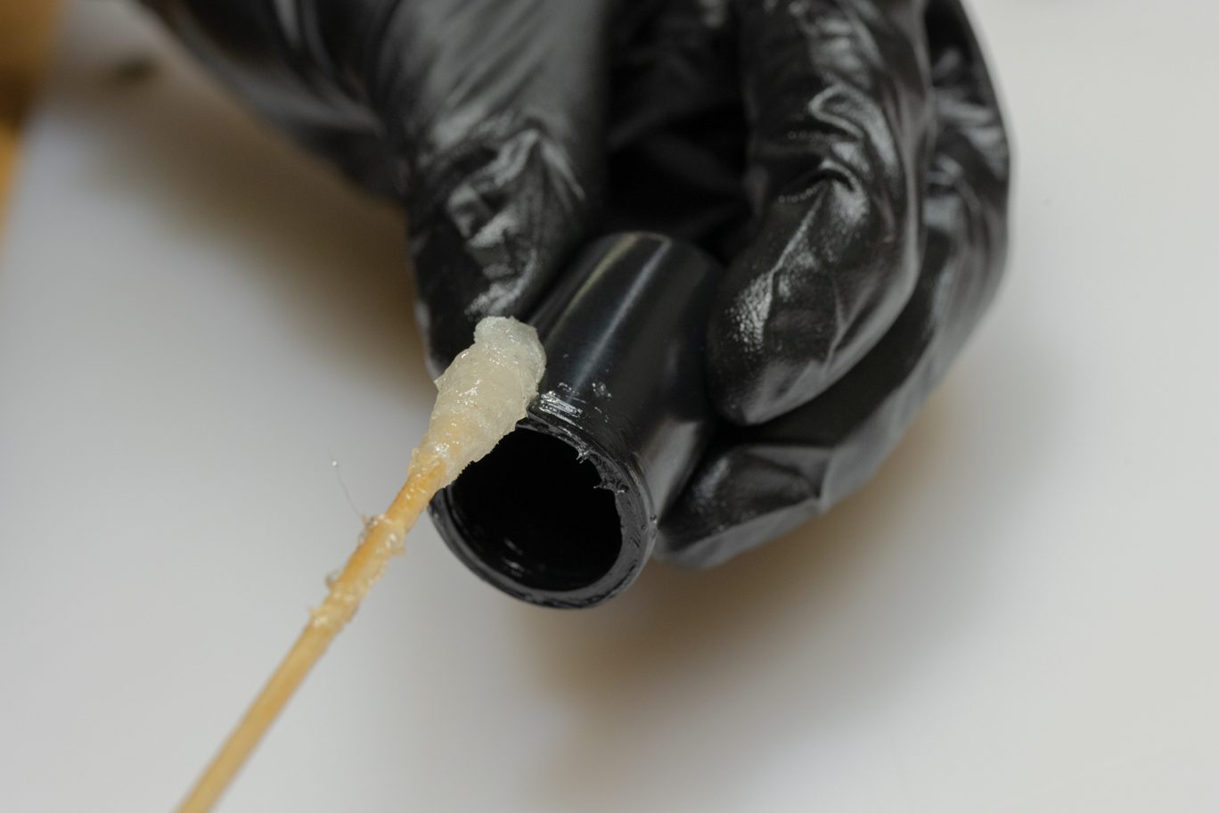
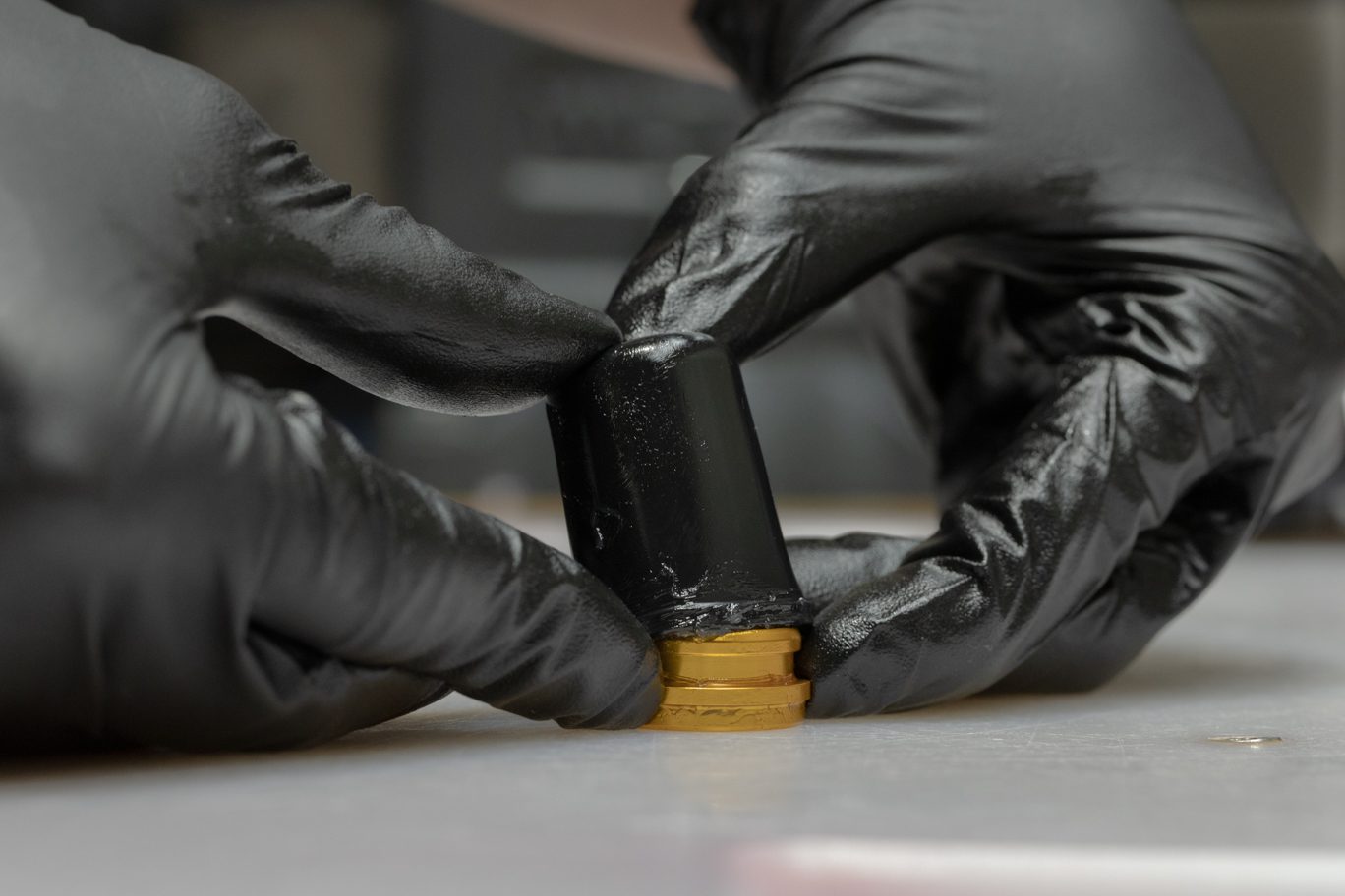
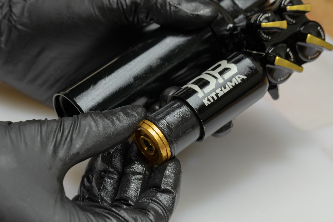
Step 12 – Air Oil Seal Head/Shaft Assembly Install
Coat piston band with shock oil. Work piston into inner damper tube. Insert inner damper tube/air oil seal head assembly into outer damper tube. Thread air oil seal head onto outer damper tube. Torque to 22 Nm with air oil seal head tool and 1/2″ crowsfoot.
TSB048 – Kitsuma Oil Seal Head Torque Valve
Coating Air Piston Band
Coating Inner Damper Tube
Air Oil Seal Head Inserted
Installing Inner Damper Tube & Air Oil Seal Head into Outer Damper Tube
Attaching Tool to Air Oil Seal Head
Torquing Air Oil Seal Head to Outer Damper Tube
Continue to Part 4
Next