

DBKitsuma Air Complete 100 & 200 Hour Service Instructions (Part 4 of 4)
Mar 2022 orig., Jul 2023 rev.
Table of Contents
Recommendations and Warnings
Cane Creek recommends only trained suspension technicians perform service on all suspension, using all required tools and following all proper procedures. Anyone without access to the proper equipment or with any concerns on the procedures should defer to an authorized Cane Creek service center for service. Improper service can result in loss of performance or suspension failure. All Cane Creek shocks have pressurized nitrogen and oil, even coil shocks. Follow the service procedures exactly as written to avoid possible injury or harm to the suspension. Always wear eye protection while performing suspension service.
Please dispose of all waste products and materials through proper channels to avoid contamination of the environment.
Any damage or issues resulting from improper service will not be covered by warranty. If you have a shock still in its original warranty period and do not wish to void your warranty, please contact an authorized Cane Creek service center.
These service instructions cover the basic service procedures using standard service kits. If your suspension requires parts beyond standard replacement parts – shaft, damper tubes, end eyes – please consult your authorized Cane Creek service center or contact us at our Cane Creek Support Center.
Service Notes
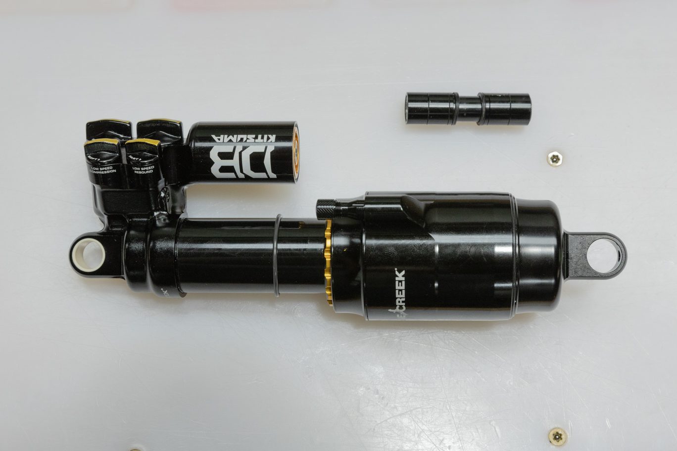
The Kitsuma Air and Coil share many service steps. Additionally, the Standard and Trunnion variants of both models have identical service procedures other than where to clamp the cylinder head. Some images in these instructions may not be identical to the valve body or outer damper tube on the Kitsuma Air, but process is the same for the shock in the image and the shock on your bench.
100 vs. 200 hour service
The only difference between the 100 hour service and the 200 hour service is whether to service or replace the Air Oil Seal Head and the Main Oil Piston. At 100 hours, those can be cleaned, serviced and reinstalled. At 200 hours, they should be replaced. If uncertain on hours, check for wear on the dual bushings inside the Air Oil Seal Head and on the piston band on the Main Oil Piston. When in doubt, replace both.
Service Kits
BCD0337 – Kitsuma Air Complete 100 Hour Rebuilt Kit (w/ Bladder)
OR
BCD0339-01 – Kitsuma Air Complete 200 Hour Rebuild Kit (w/ Bladder) – includes new Air Oil Seal Head & Main Oil Piston
BCD0169 – Bladder Res End Cap (if replacing older IFP system)
Required Cane Creek Tools
ACD0354 – Bladder Res End Fill Tool
AAD1361-01 – DBCoil/ DBAir – Oil Fill Needle Adapter
DBT016 – DB Gas Fill Needle
AAD0555 – 8mm & 9.5mm Shaft Clamp
AAD2465 – Kitsuma Valve Seat Tool
ACD0322 – Kitsuma Low Speed Detent Funnel
BAD1298 – DB 9.5mm Shaft Bullet
ACD0334 – Kitsuma Air Oil Seal Head Tool
BCD0344 – Kitsuma/DBair/DBair IL Air Seal Head Tool
DBT012 – DB IFP Setting Tool
Additional Tools & Supplies
Allen wrenches – 3 & 4mm
Torx wrenches – T10 & T20
Sockets – 4, 8 & 13mm
Crowfoot wrenches – 1/2″ & 32mm
9.5mm Shaft Bullet
Torque wrenchesKnipex pliers
Pick
Strap wrench
Suspension Grease
PolyLube Grease
Motorex 4wt Racing Fork Oil
Royal Purple 10w-30
Vacuum Oil Fill Machine
Nitrogen Fill System
Torque, Loctite, Oil & Nitrogen Specs
Torque & Loctite Chart
| Part | Torque Spec | Loctite Spec |
|---|---|---|
| Shaft Bolt | 5 Nm | 243 (Blue) |
| Outer Damper Tube | Tight | 263 (Red) |
| Valve Seat | 4.8 Nm | None |
| High Speed Adjuster | 7 Nm | None |
| Climb Switch Screw | 1.2 Nm | 243 (Blue) |
| Oil Seal Head | 22 Nm | None |
| End Eye | 4.8 Nm | 243 (Blue) |
| Inner Air Can/Air Seal Head | 22.6 Nm | None (PolyLube) |
Oil Chart
| Oil Location | Oil Type | Oil Amount |
|---|---|---|
| Air Can | Royal Purple 10w-30 | 5 mL |
| Damper Fill | Motorex 4wt Racing Fork Oil | Fill to 3 Bars |
Nitrogen Chart
| Nitrogen Location | Nitrogen Pressure |
|---|---|
| Valve Body | 11 - 12 Bars |
Damper Fill
Step 1 – Prepping Shock for Fill
Lightly grease and install new fill port o-ring (AAD0012). Temporarily reinstall end eye. Thread fill nozzle onto valve body. Back all adjusters to fully open and open Climb Switch. Fully compress damper. Attach bladder fill tool with spacer. Attach oil fill machine to fill port per your manufacturer’s instructions.
Fill Port O-Ring installed
Attaching End Eye
Attaching Fill Adapter
Attaching Bladder Fill Tool
Attaching Bladder Fill Tool Spacer
Attached to Fill Machine

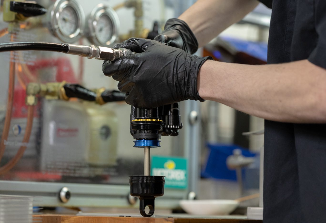
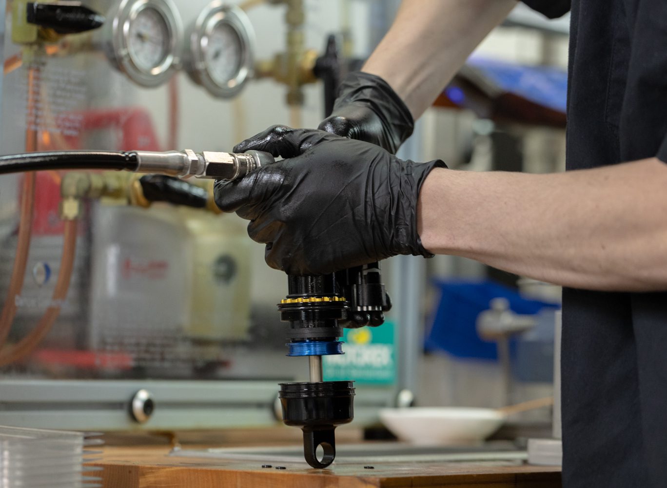
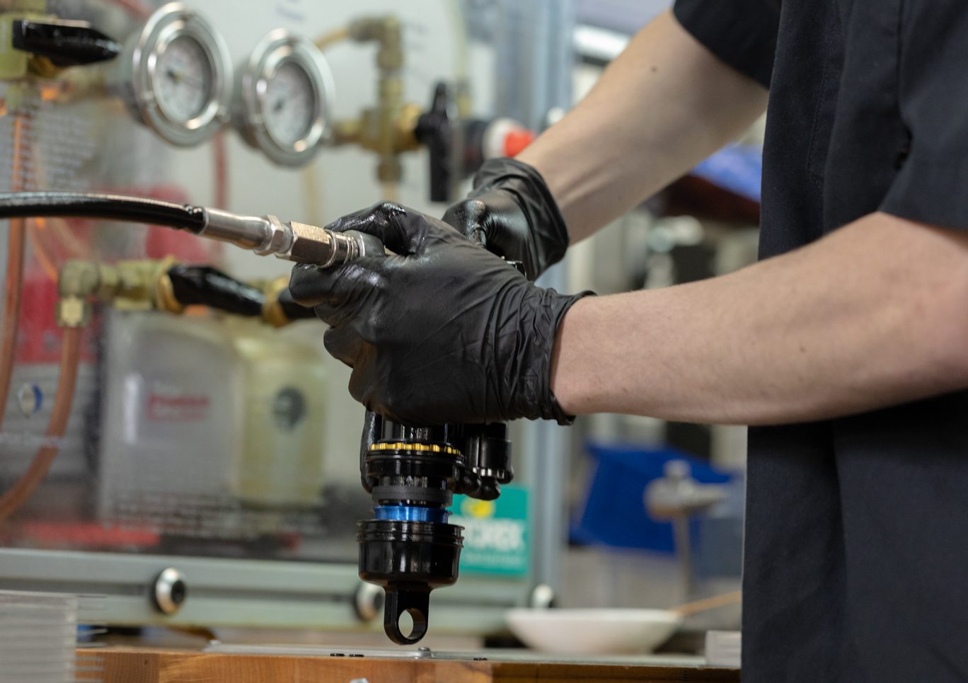
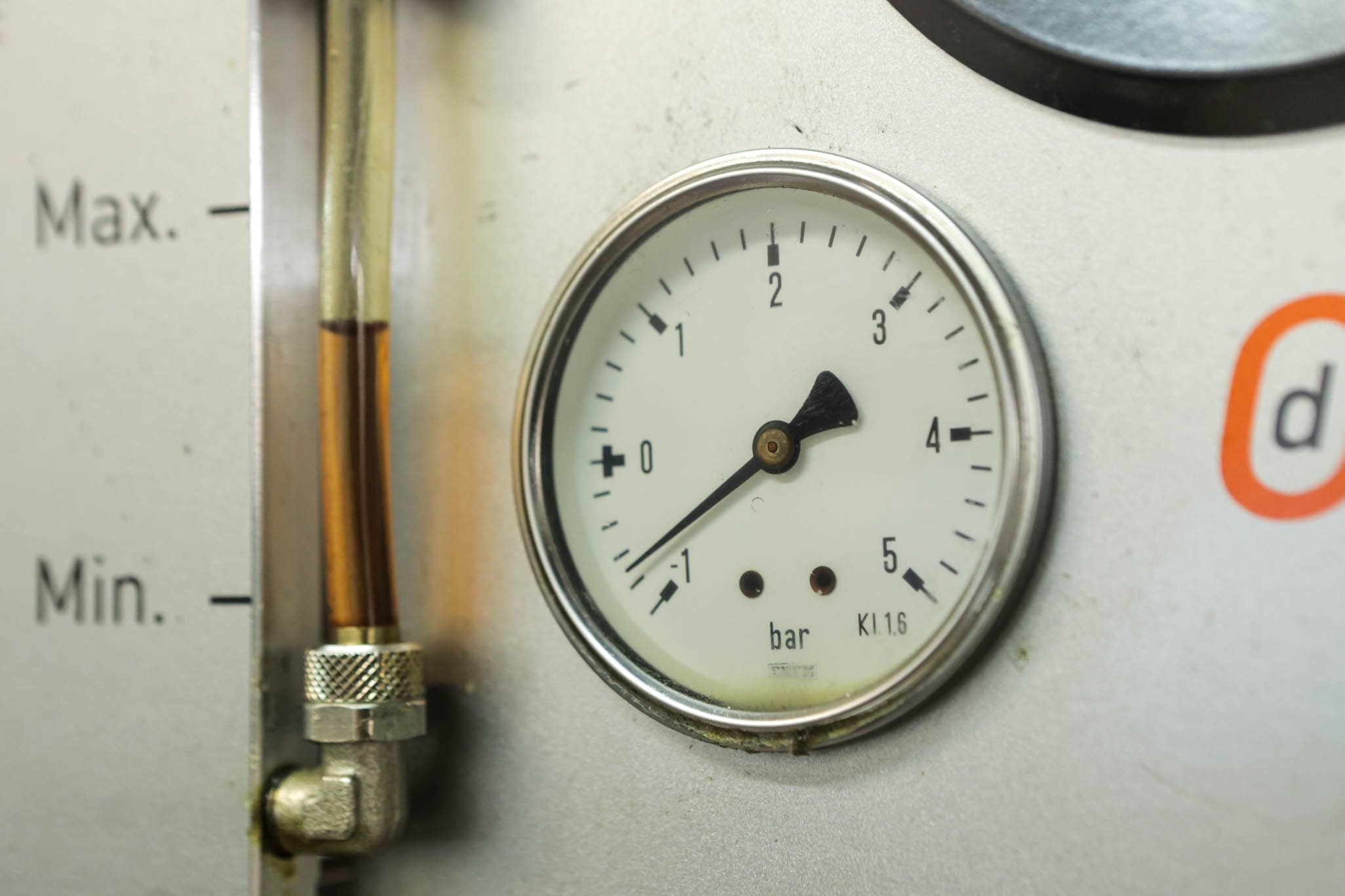
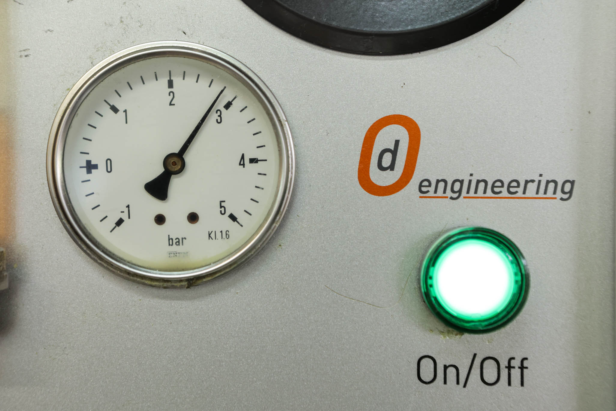
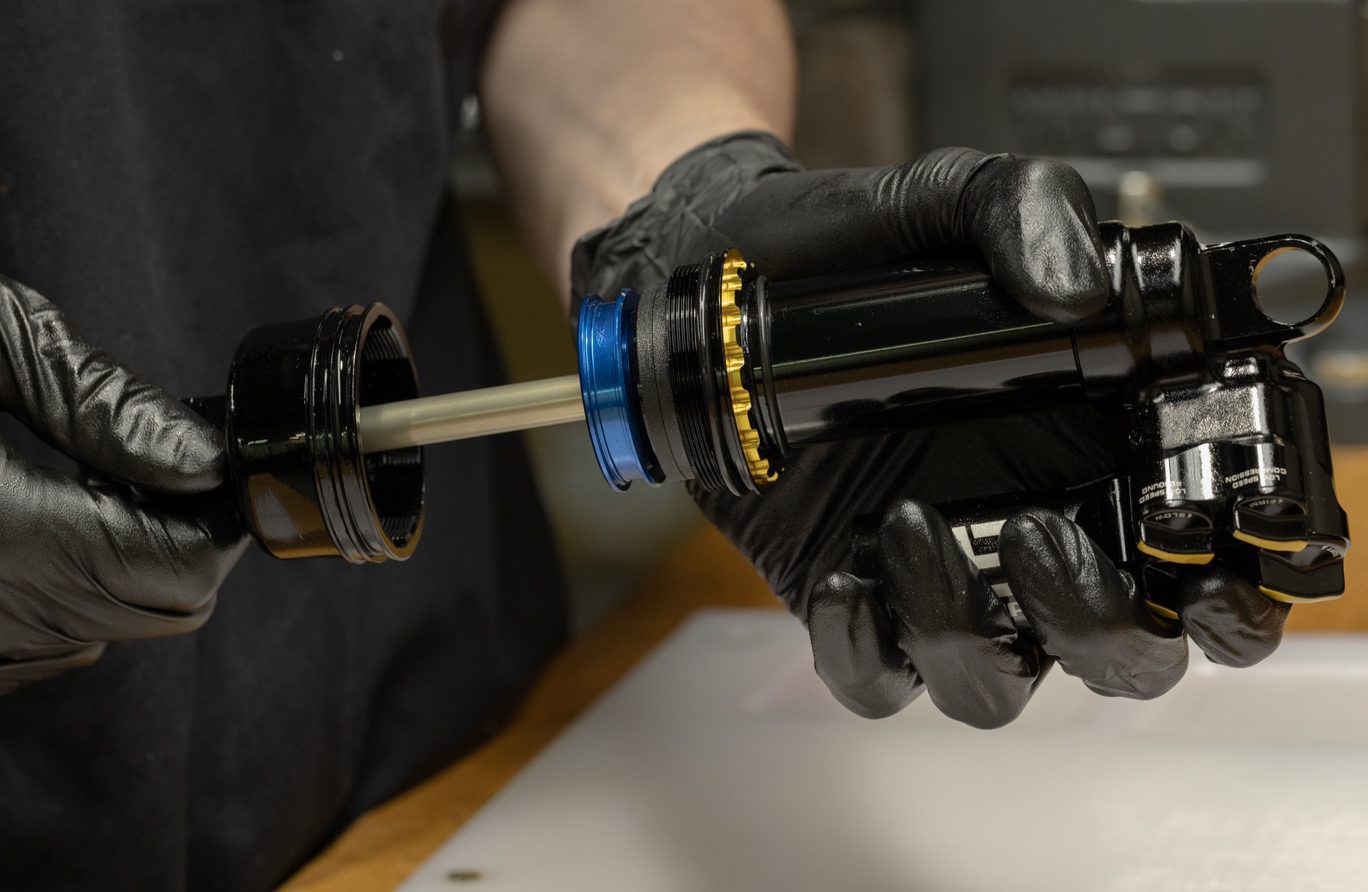
Step 2 – Vacuum and Oil Fill Process
Vacuum system to (4) mbar. Pressure with Oil to (3) bar. Slowly cycle shaft finishing with shaft fully out. Cut fill and equalize pressure. Vacuum system to (4) mbar, leaving shaft out. Pressure again with Oil to (3) bar. Slowly cycle shaft finishing with shaft fully out. Cut fill.
Vacuum System to (4) mbar
Oil Fill Cycle 1
Oil Fill Cycle 2
Oil Fill Cycle 3
Oil Pre-Fill
Oil Fill to (3) bar
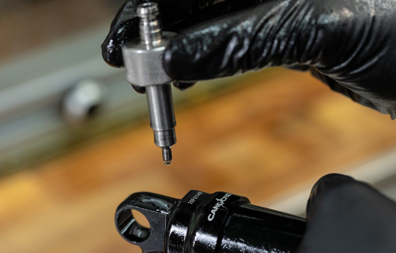
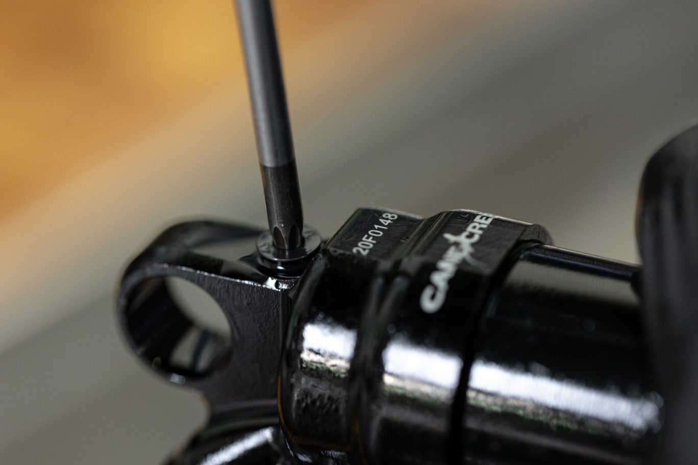
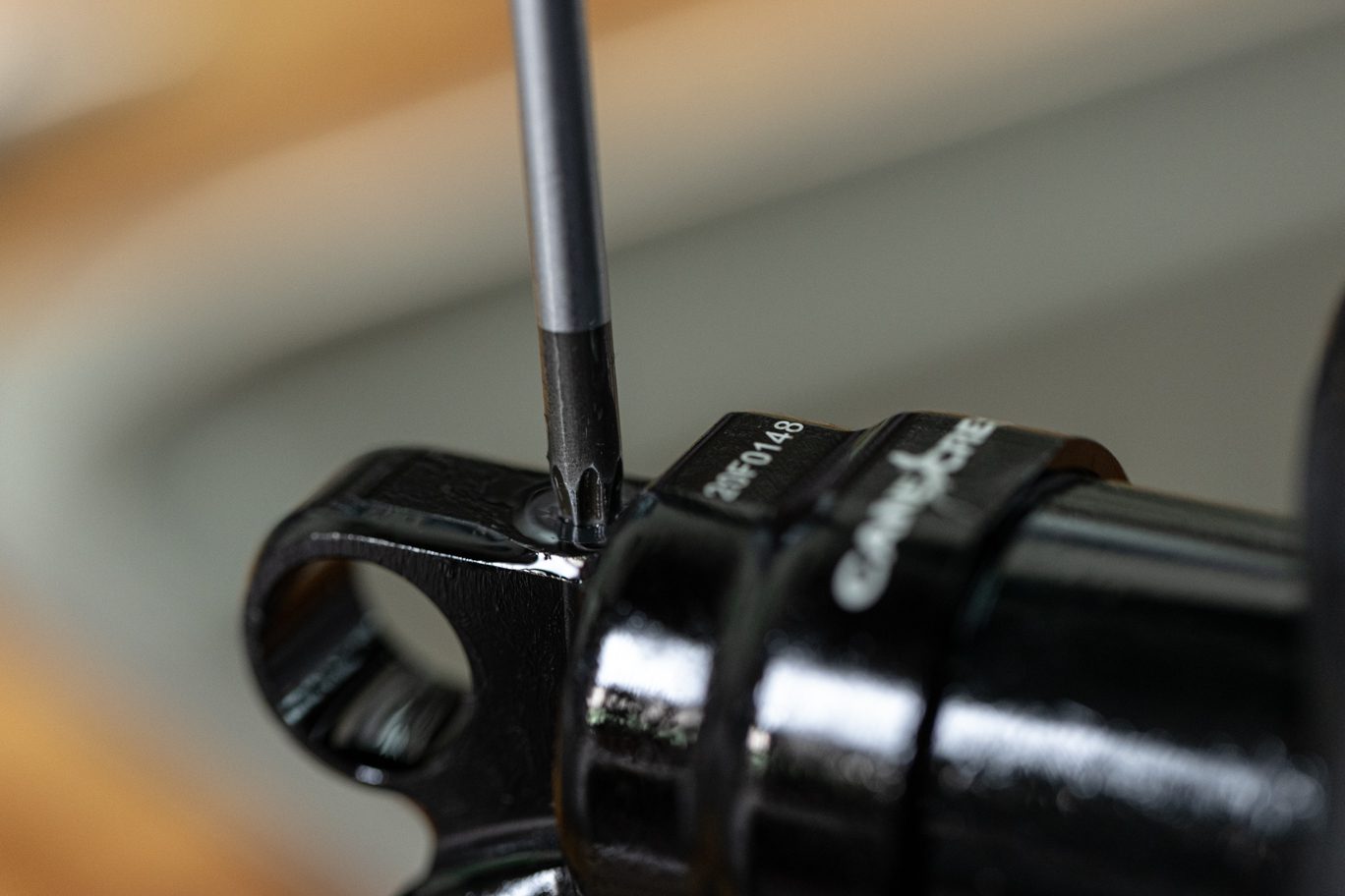
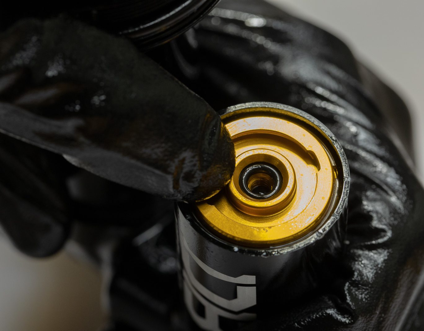
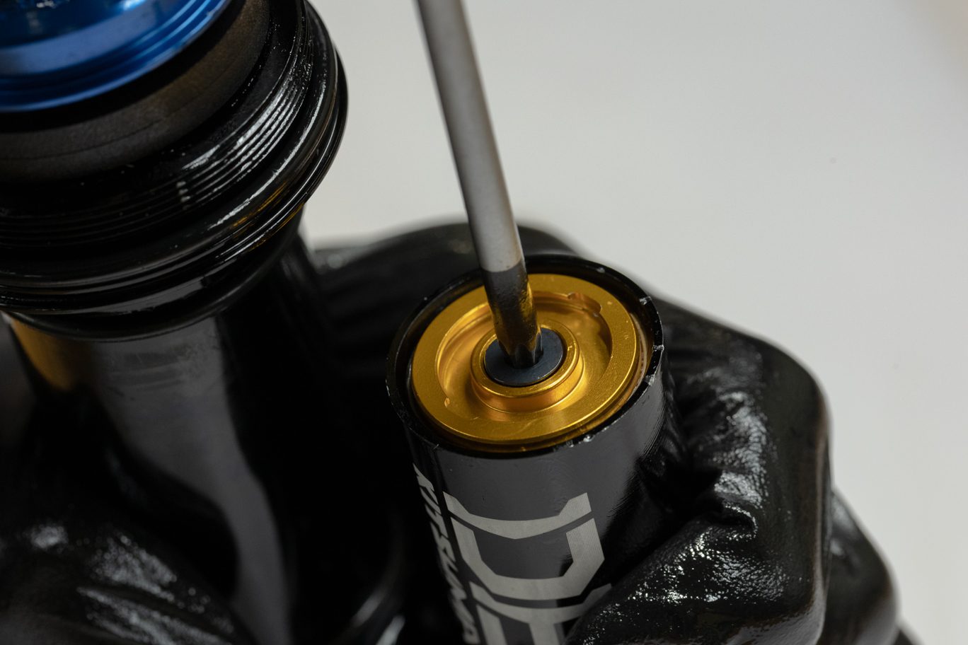
Step 3 – Valve Body Closure
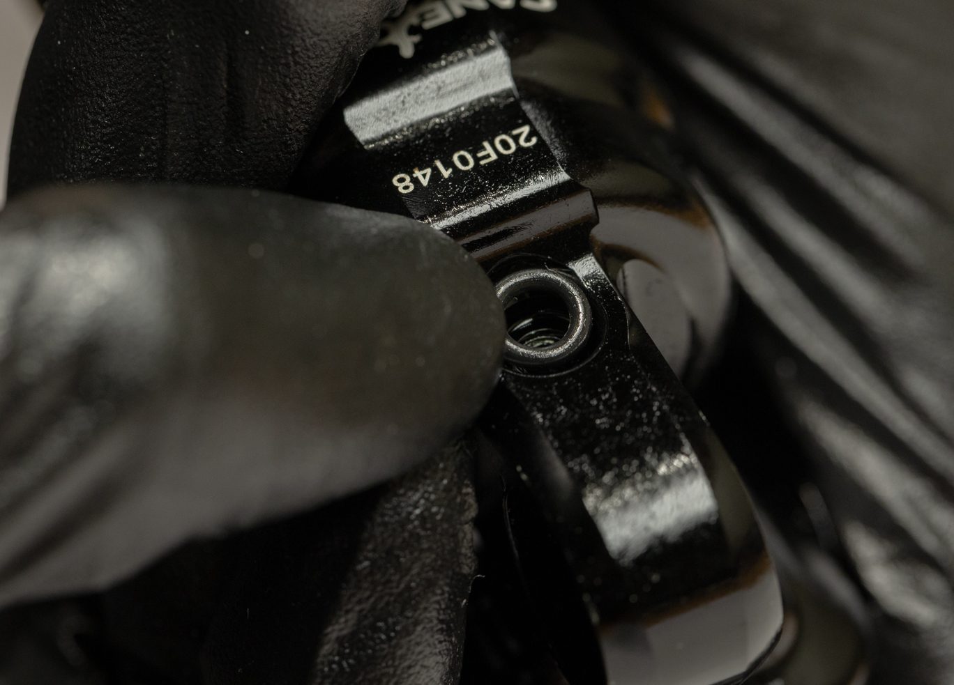
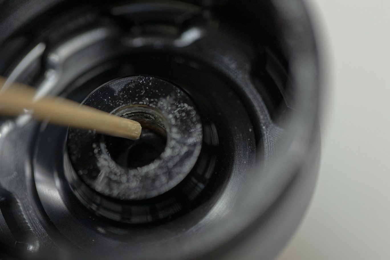
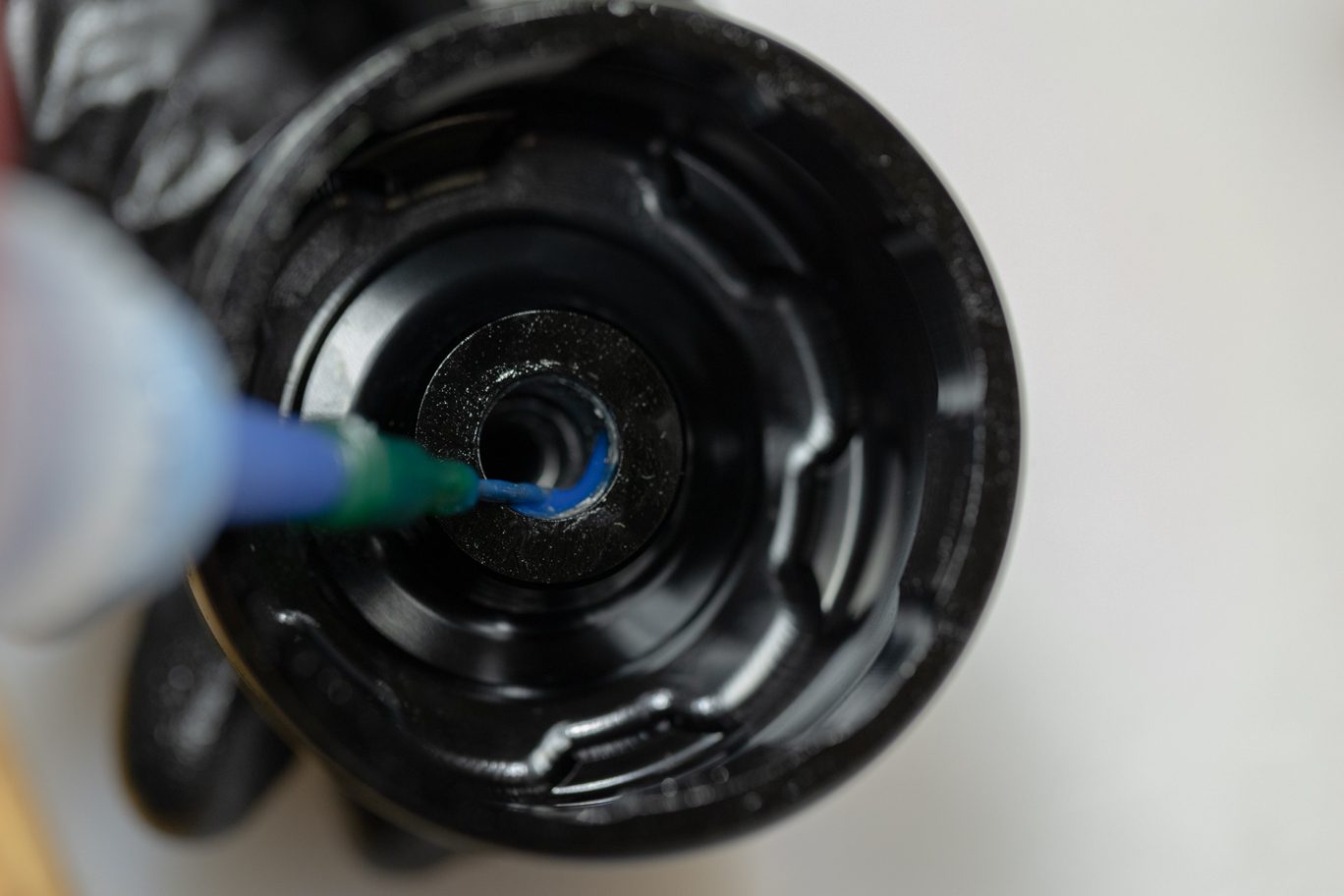
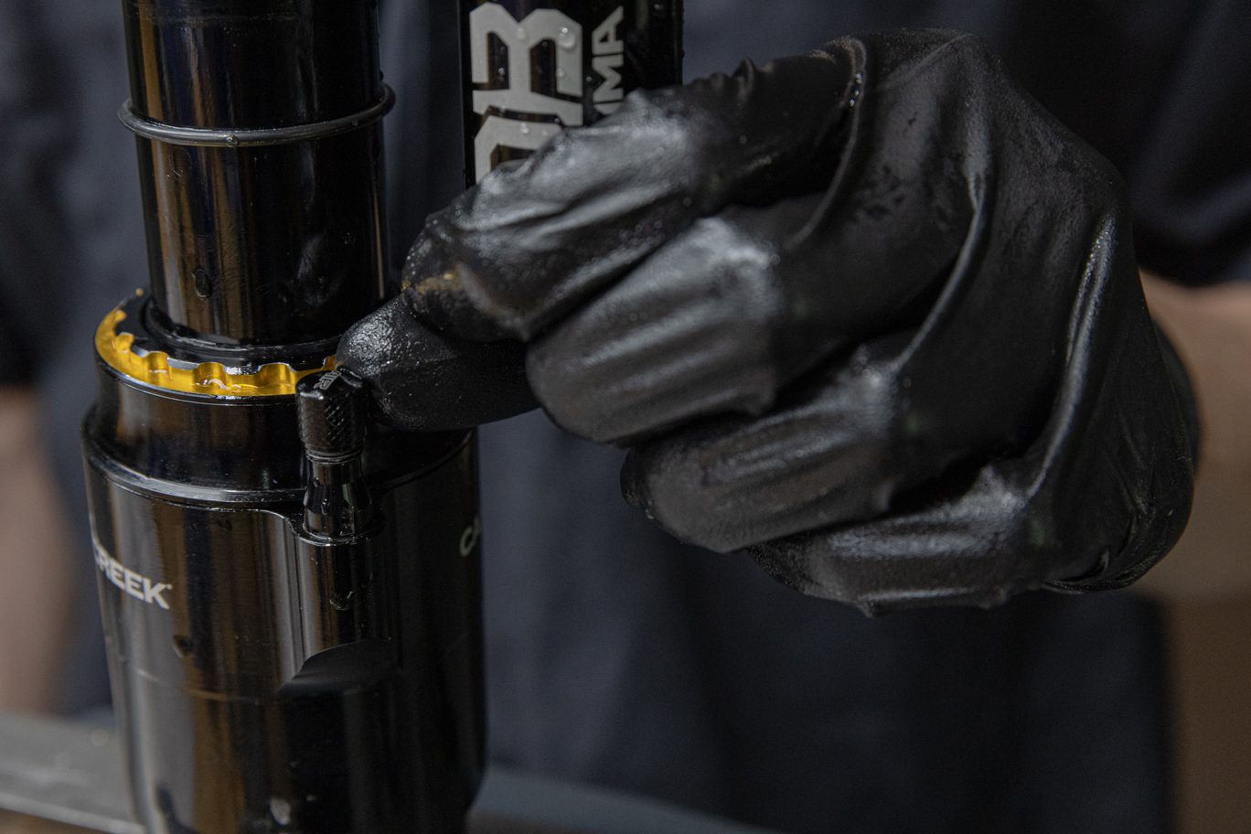
Holding horizontal, disconnect fill machine. Drip some oil on to top of fill. Install oil fill screw with T20. Remove bladder fill tool.
Removing Oil Fill Adapter
Installing Oil Fill Screw
Oil Fill Screw Installed
Removing Bladder Fill Tool Spacer
Removing Bladder Fill Tool
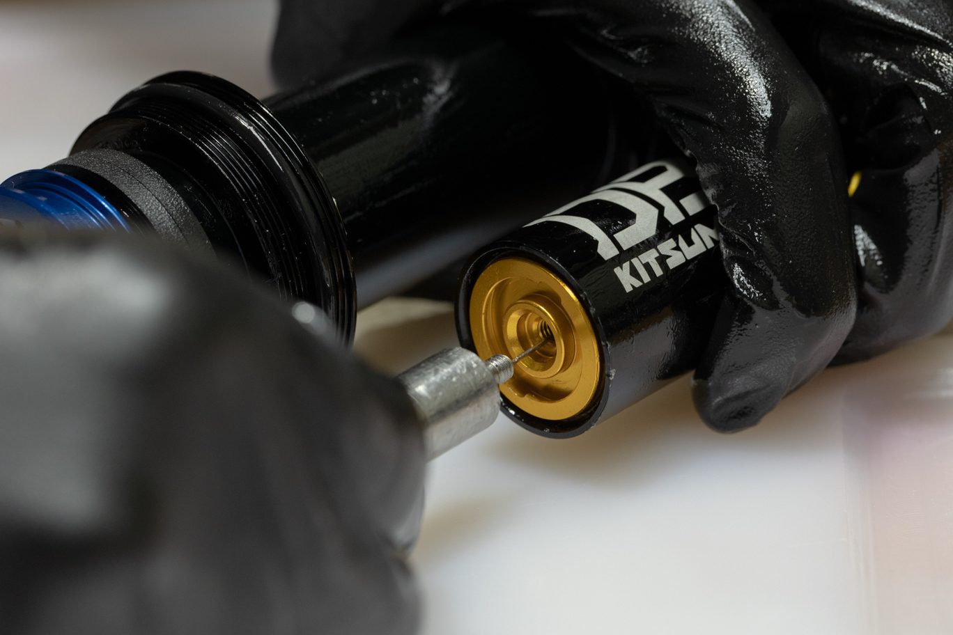
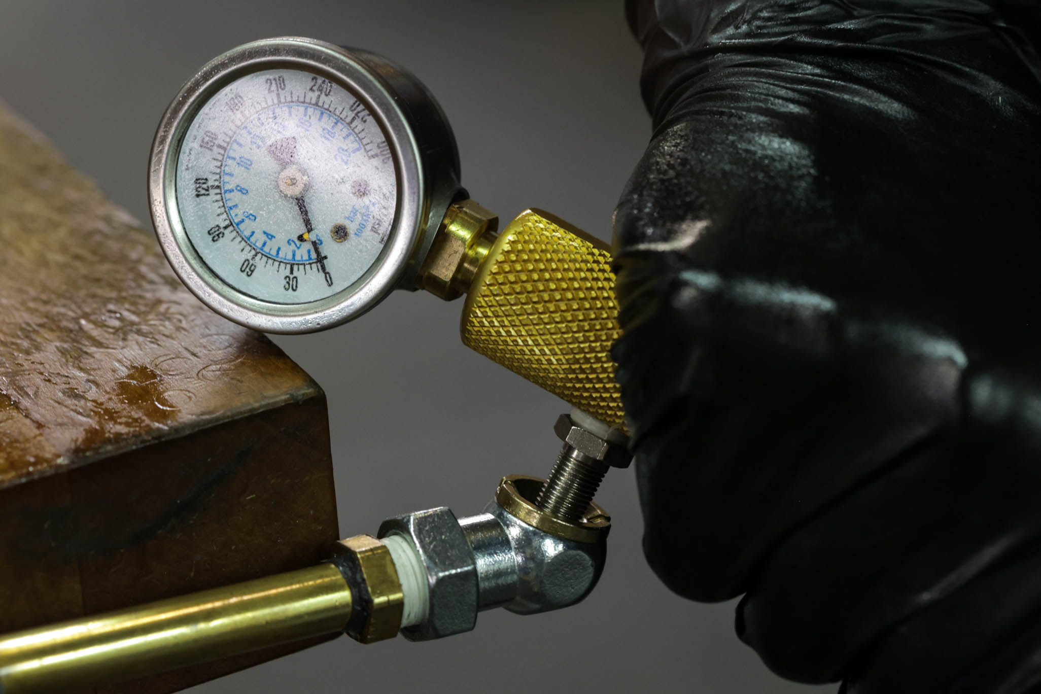
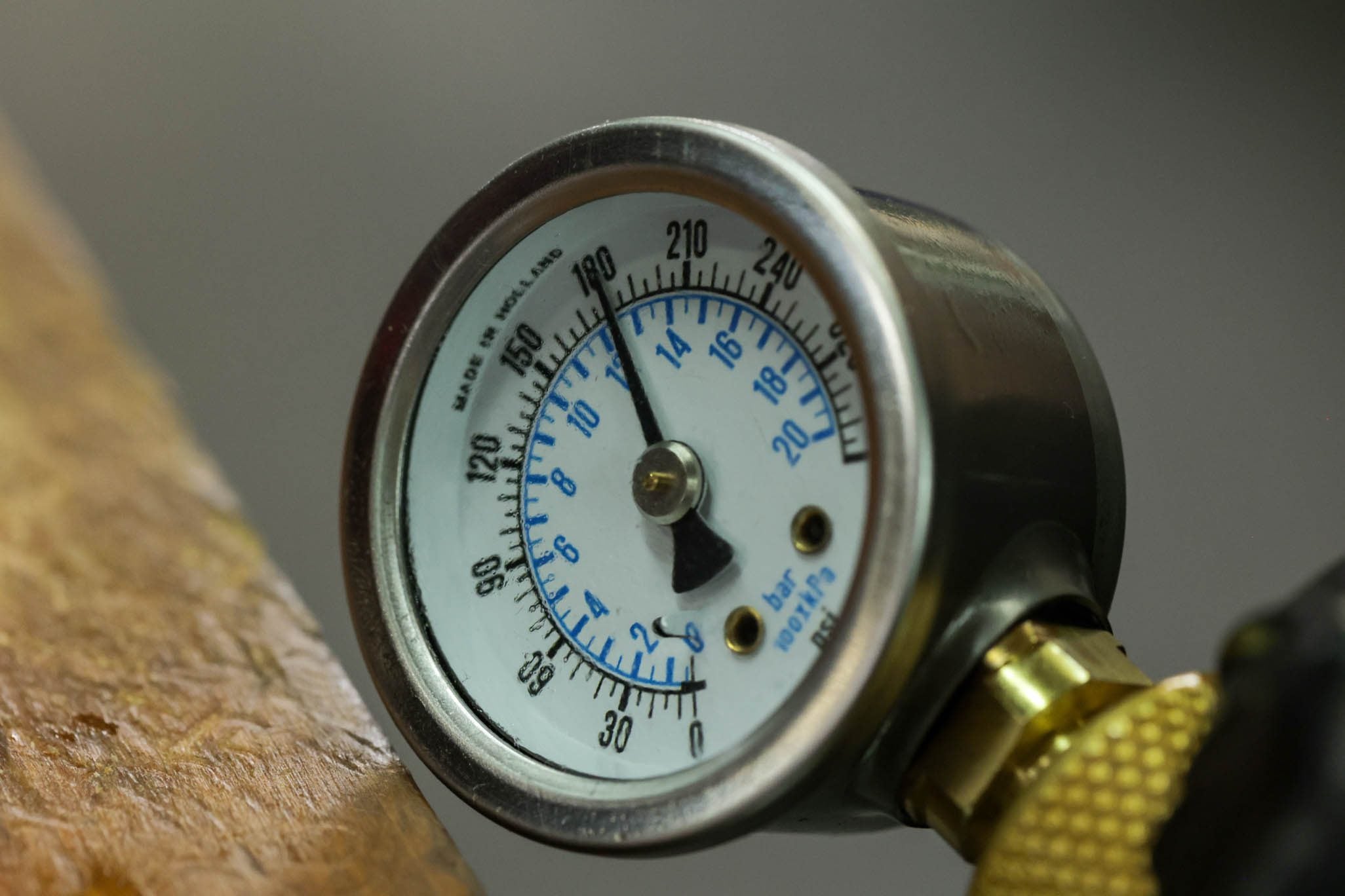
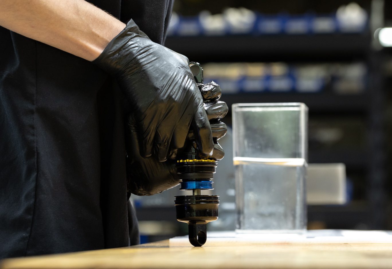
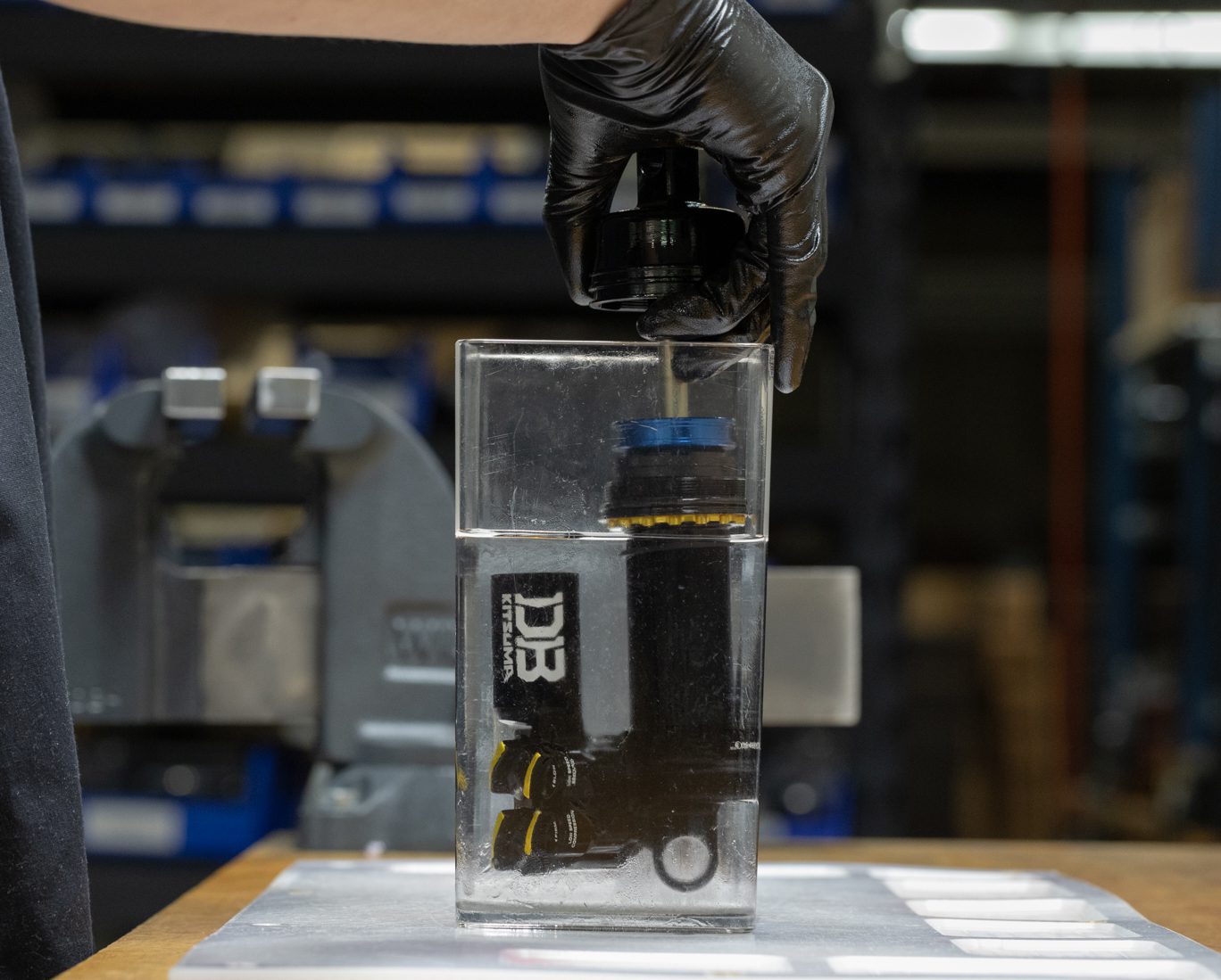
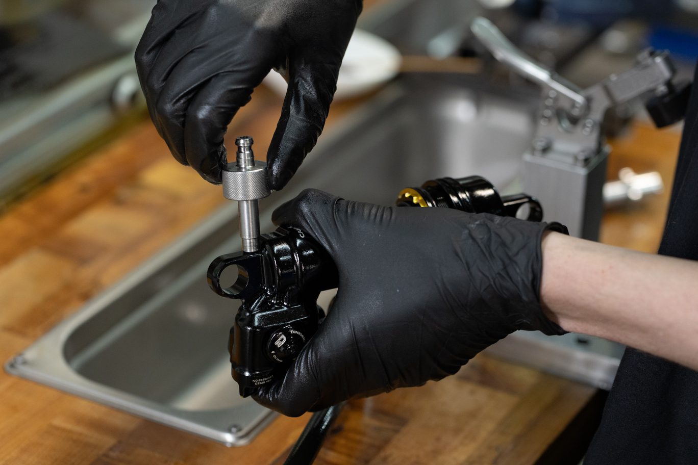
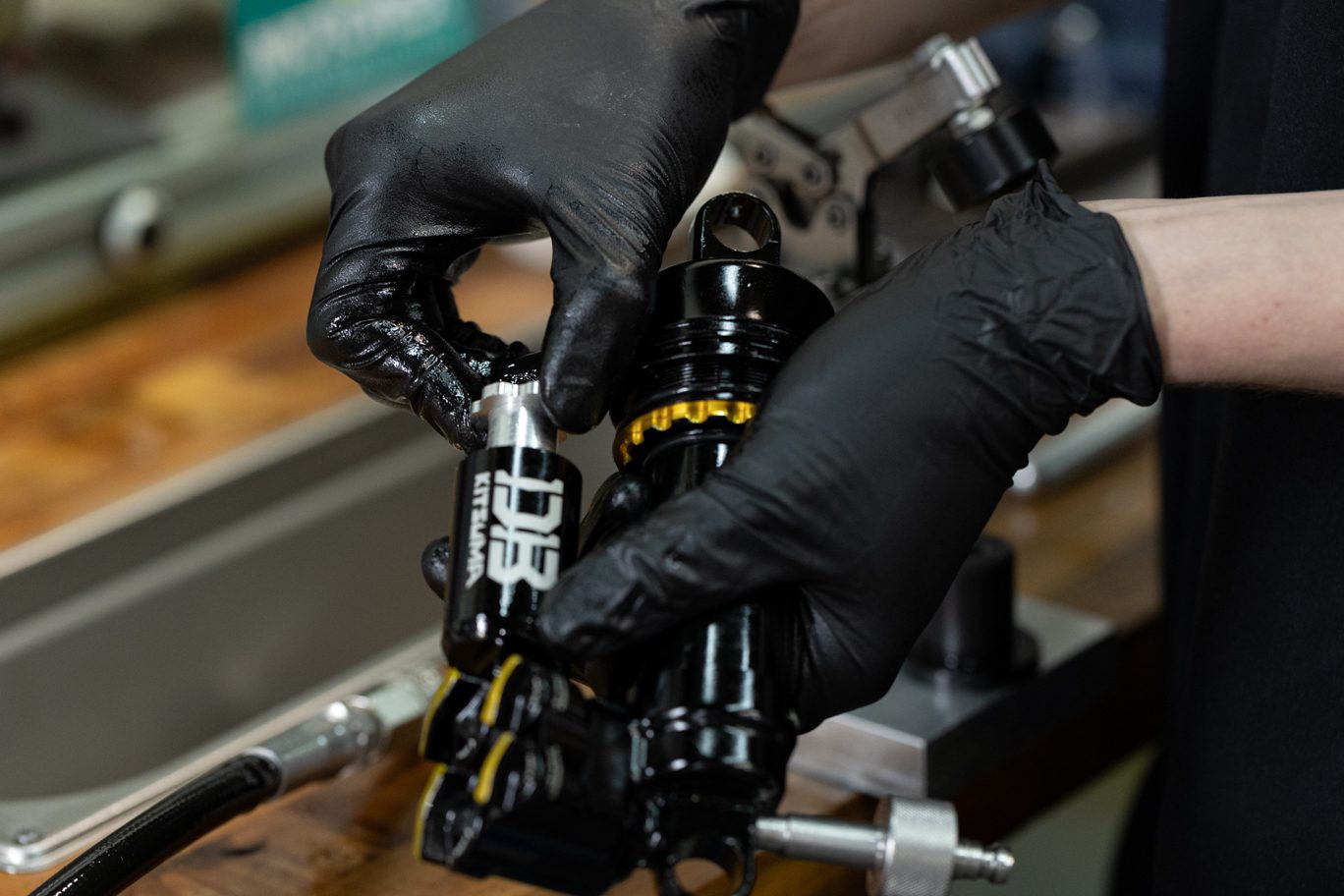
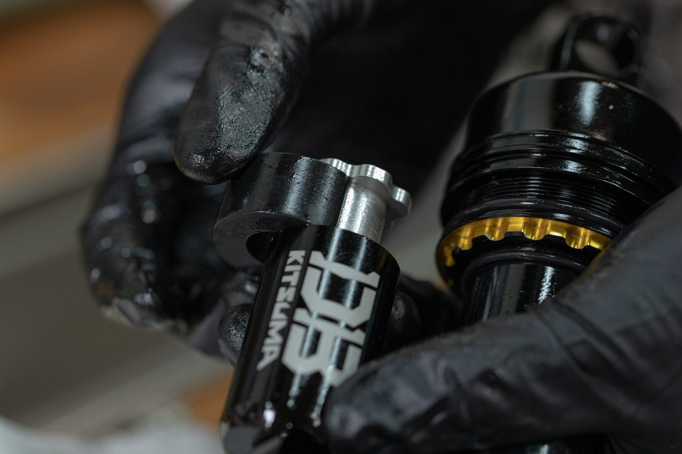
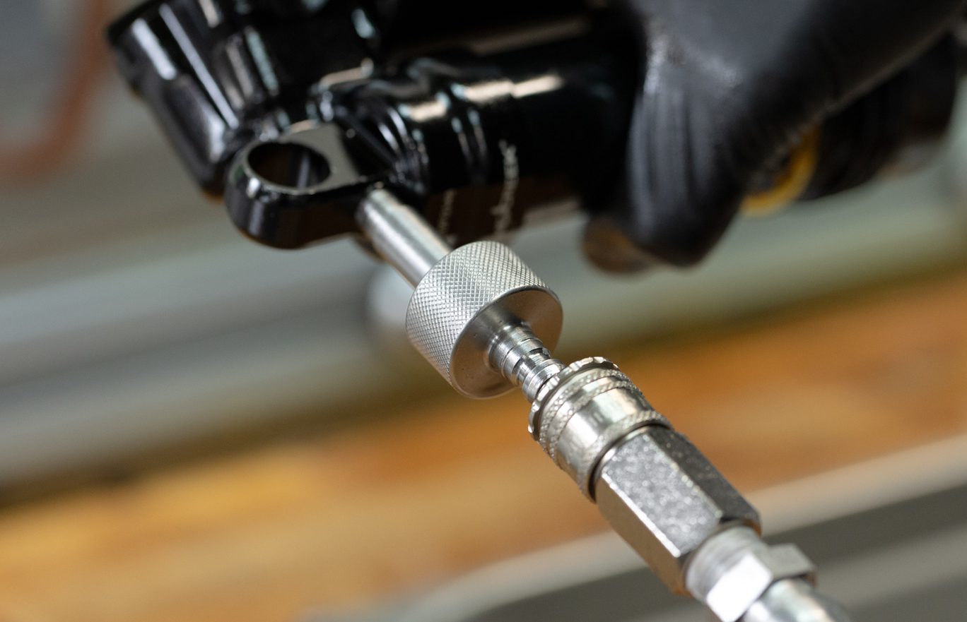
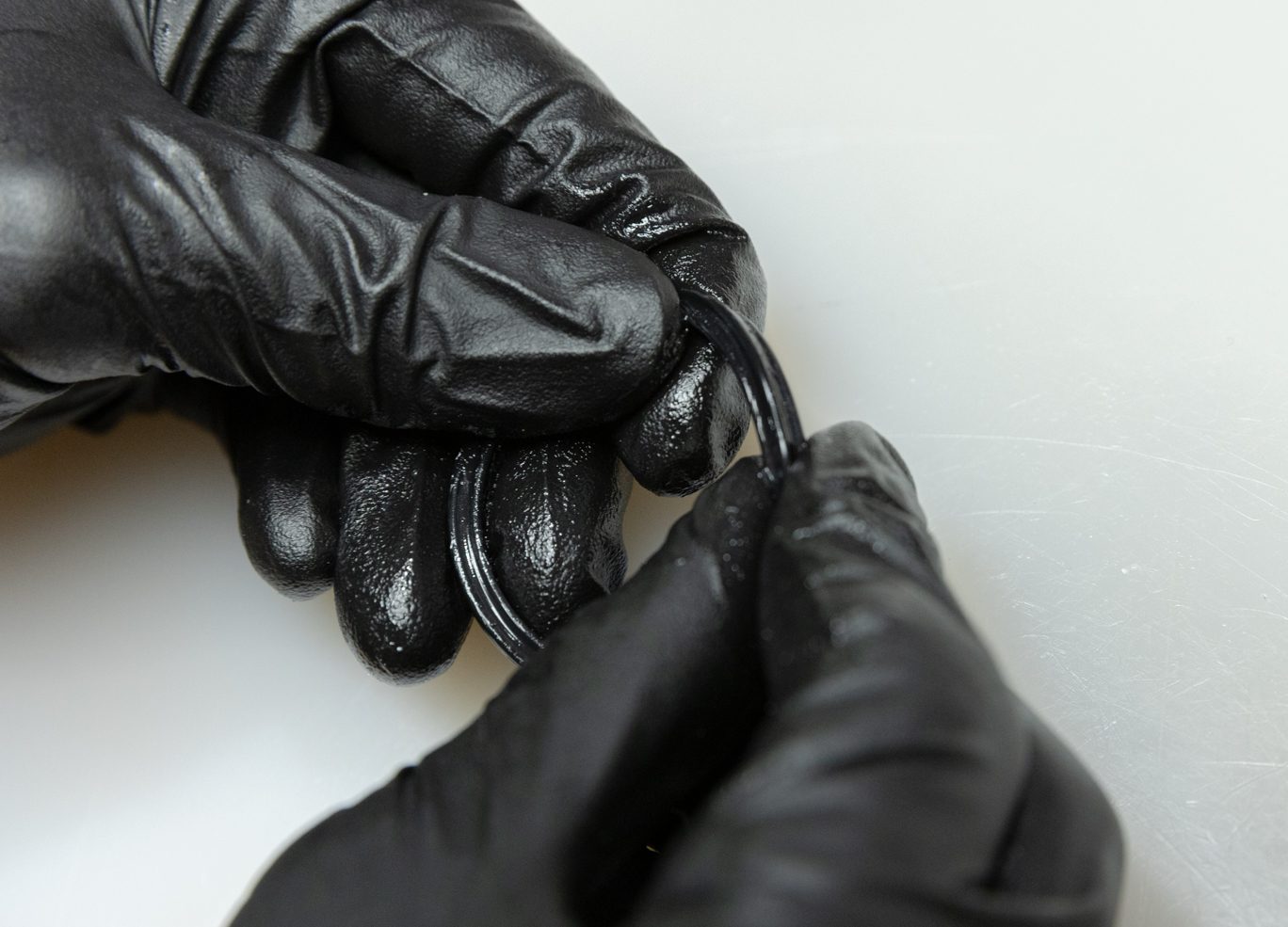
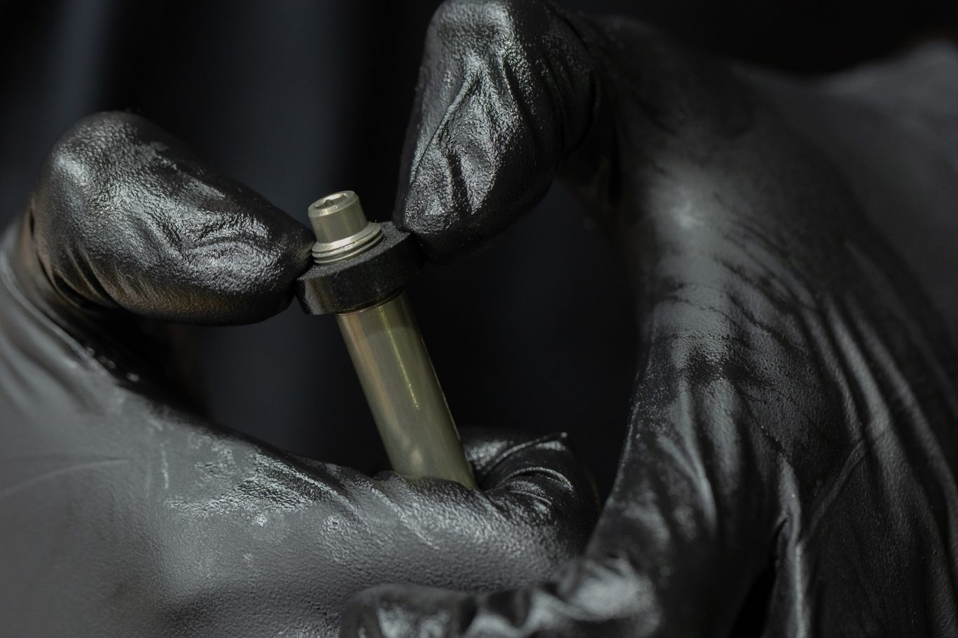
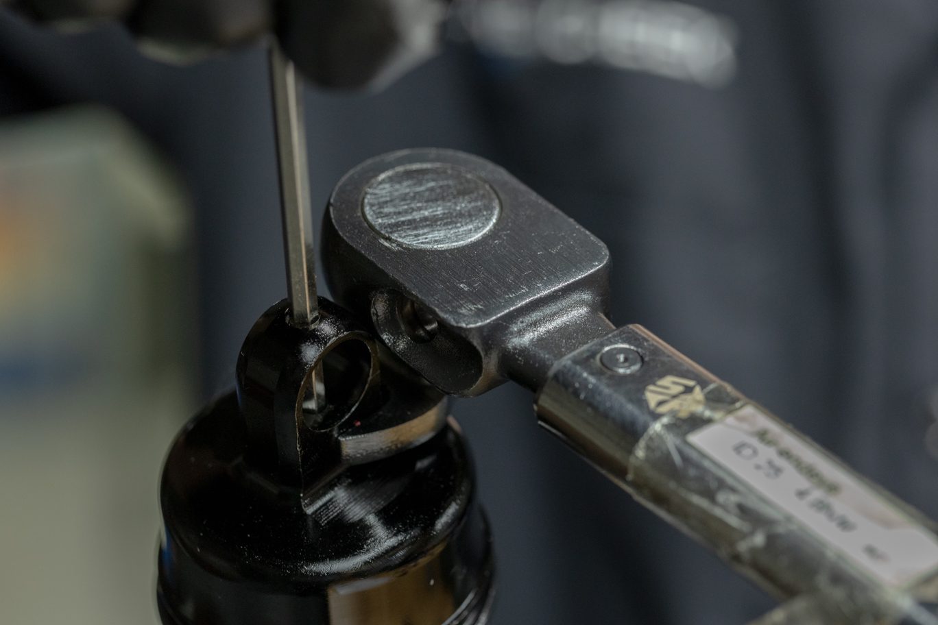
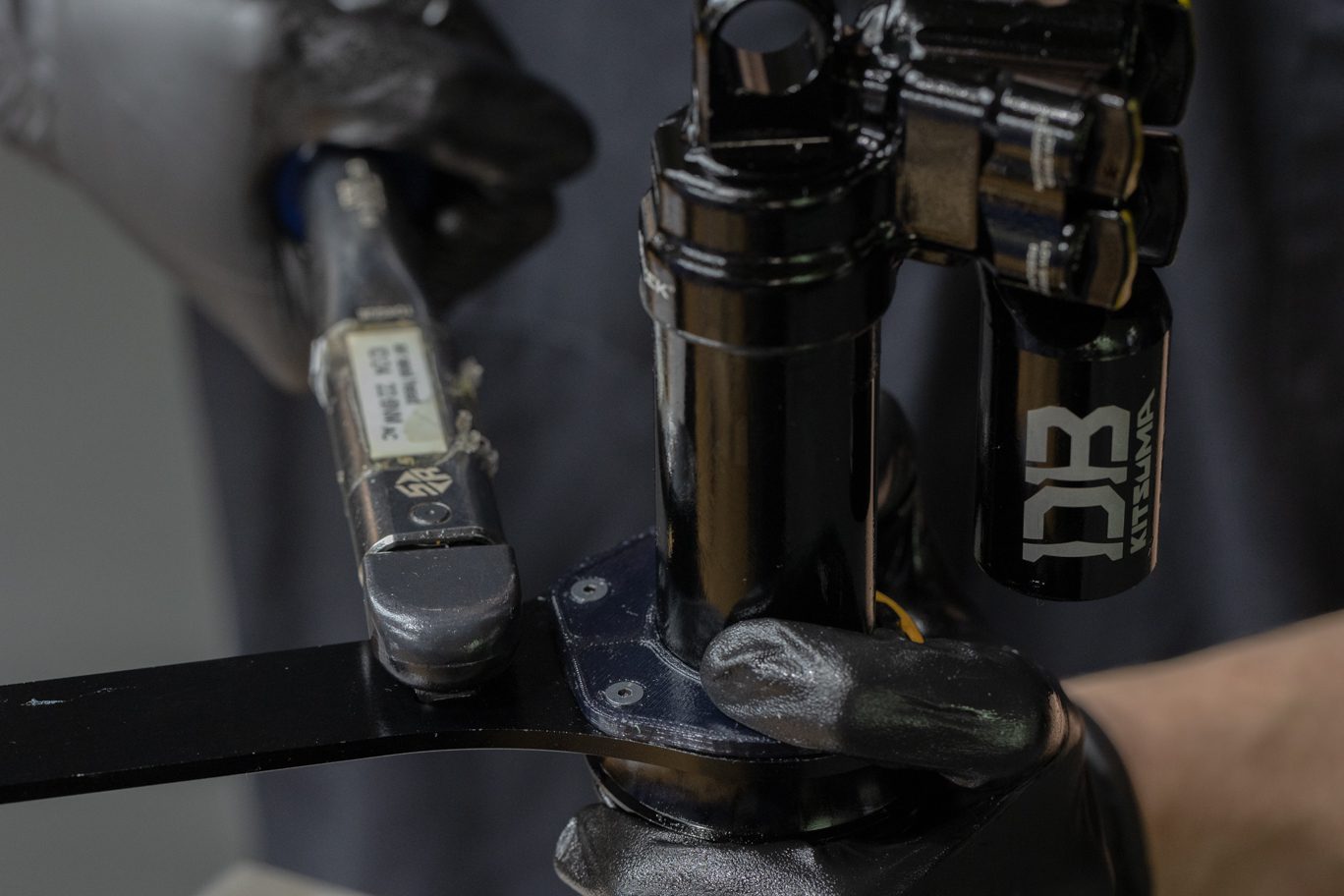
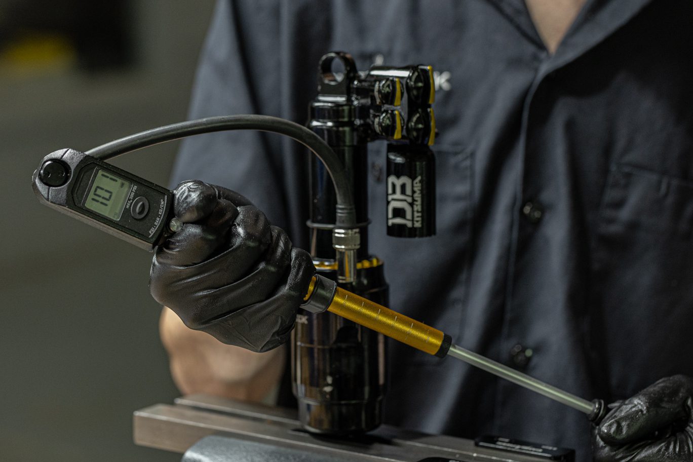
Step 4 – Nitrogen Fill
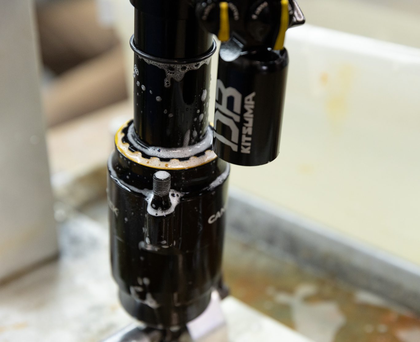
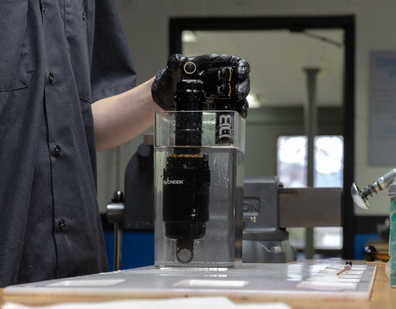
Insert gas fill needle in gas fill port on reservoir end cap. Pressurize to 11-12 bars of nitrogen. Compress shaft and ensure proper gas by observing shaft return to full extension. Submerge valve body in water to check for gas leaks. Install new res end cap o-ring (.DB11102) and fill screw.
If mechanical dyno equipment is available, run shock on dyno at this point.
Insert Nitrogen Fill Needle
Connect to Nitrogen Hose
Nitrogen Filled to Pressure
Compression Test
Leak Test
Fill Screw O-Ring Install
Fill Screw Install
Air Can Reassembly
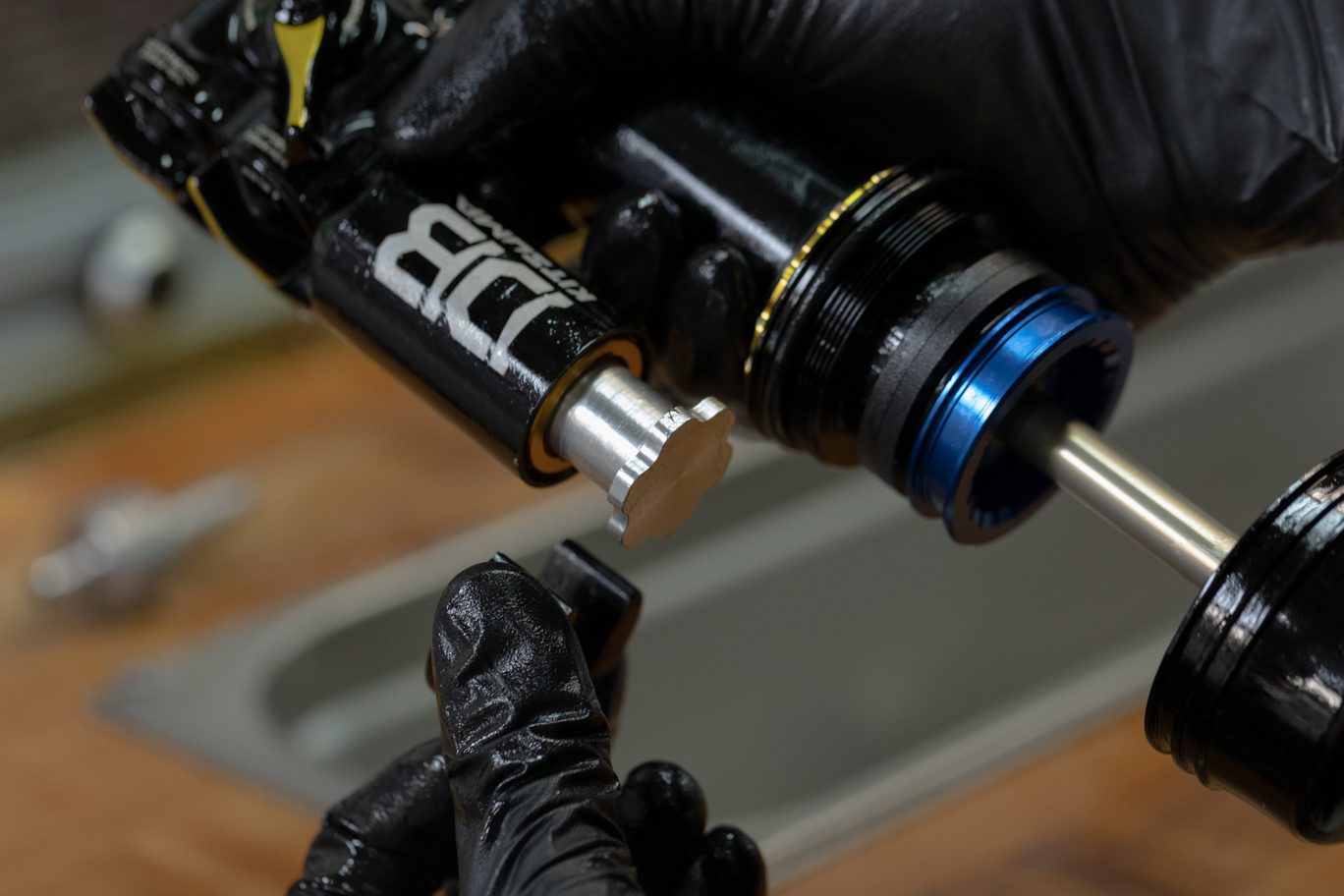
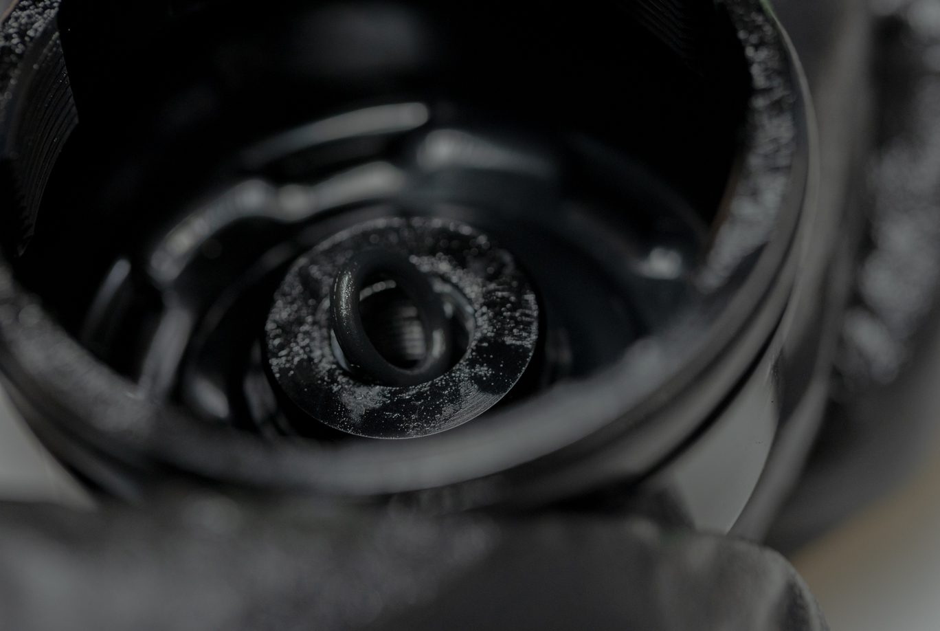
Step 1 – Air Piston Reassembly
Remove end eye from shaft. Clamp shock in vise. Thoroughly grease all four sides of air piston quad ring (AAD2184). Grease the quad ring channel on the air piston. Install first air piston L-ring (ACD0132), quad ring and second L-ring with flat side of L-rings towards quad ring.
Greasing Air Piston Quad Ring
Greasing Air Piston Quad Ring Channel
First Air Piston L-Ring Install
Air Piston Quad Ring Installed
Second Air Piston L-Ring Install
Air Piston Assembled
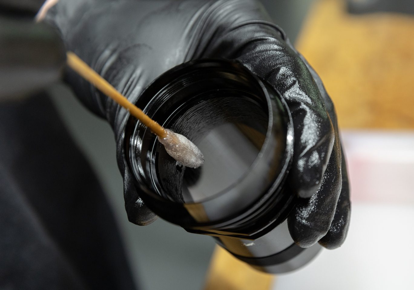
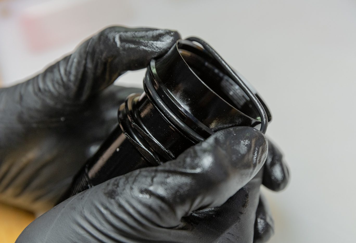
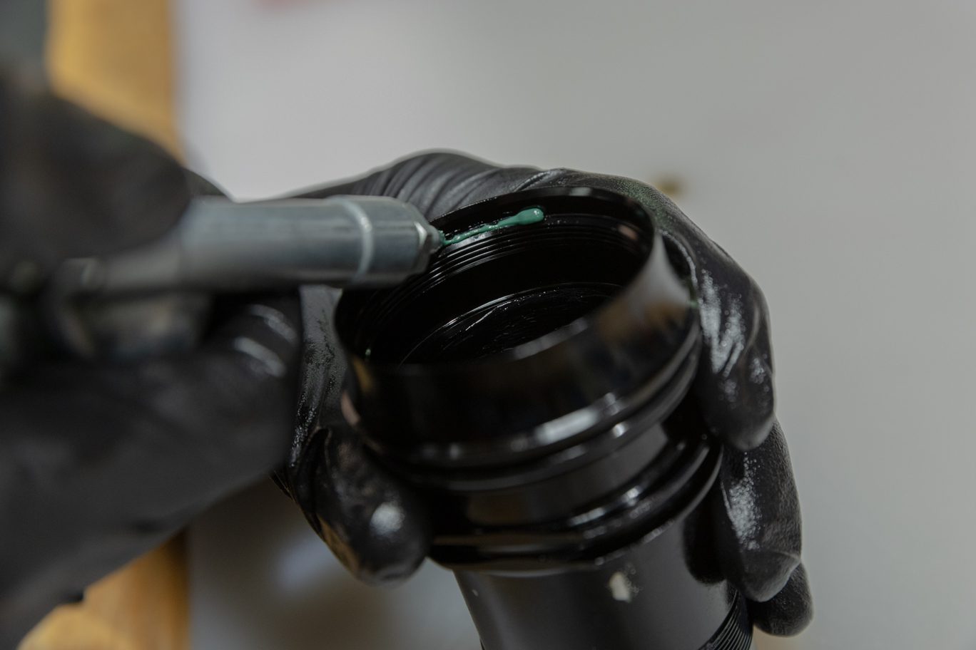
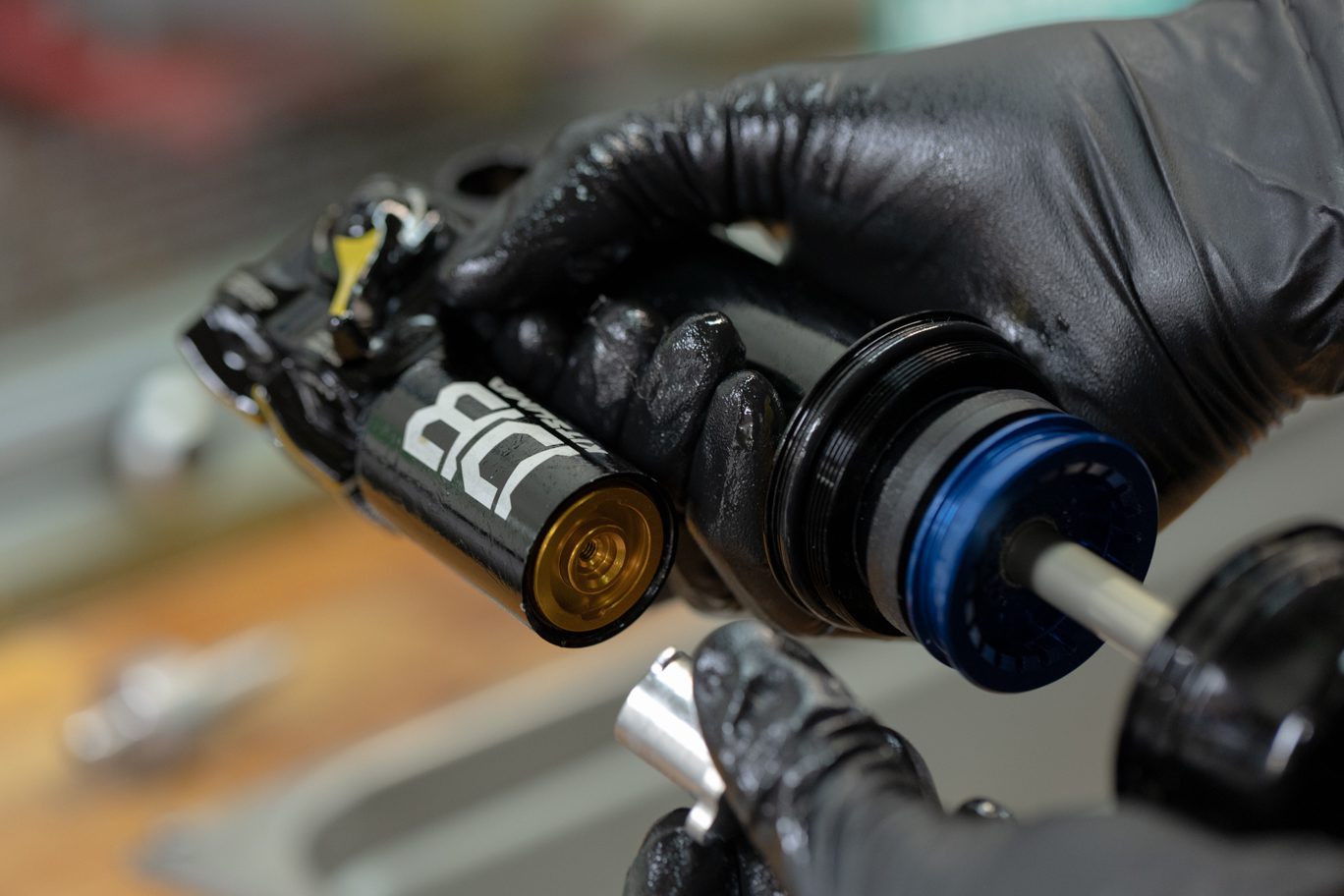
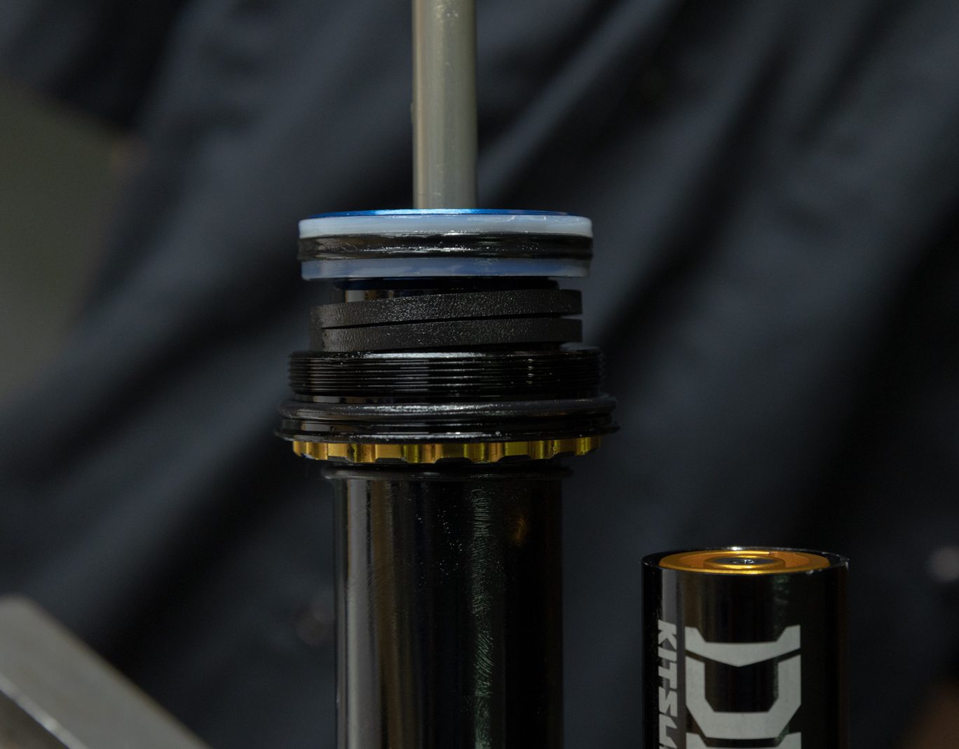
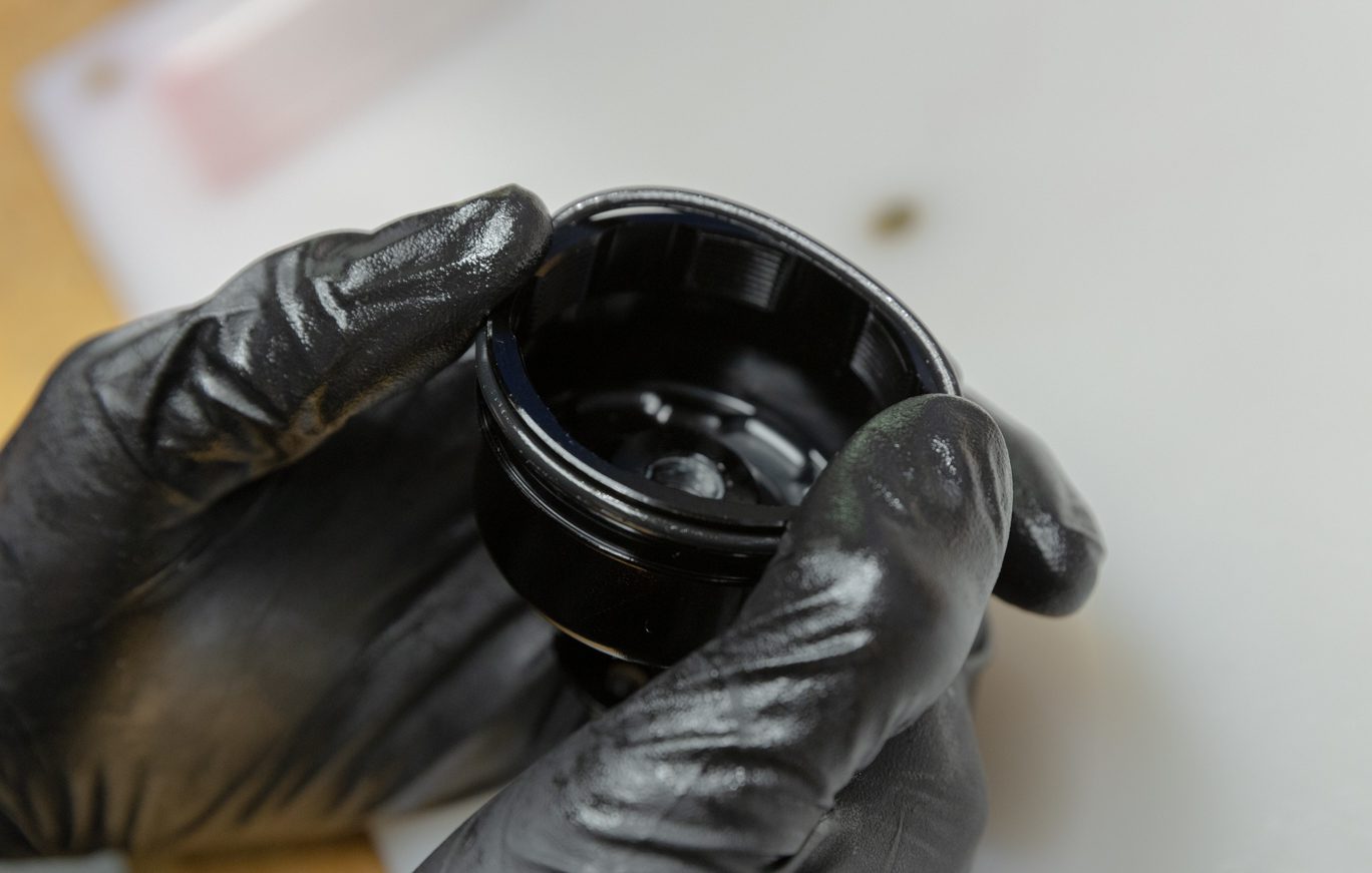
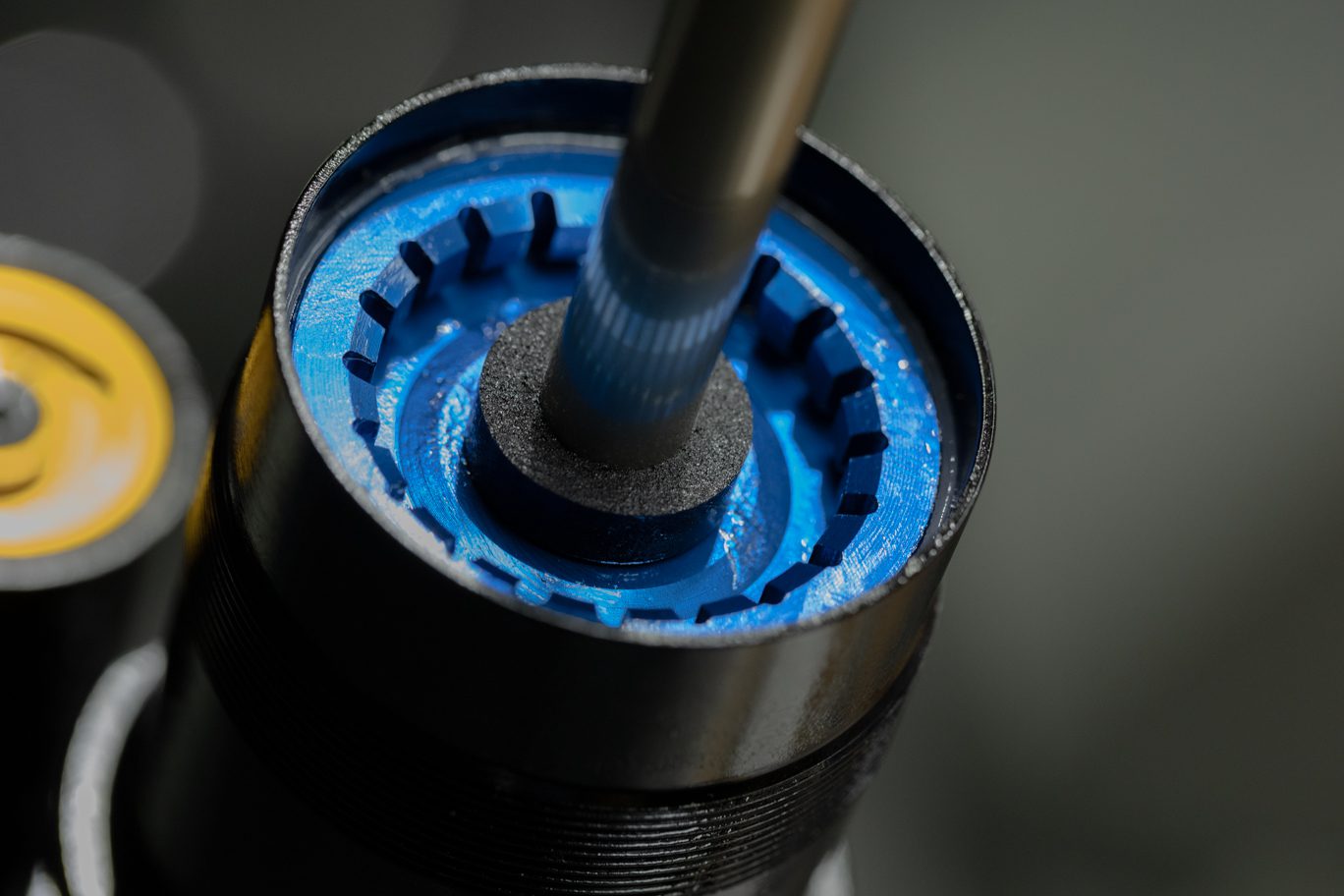
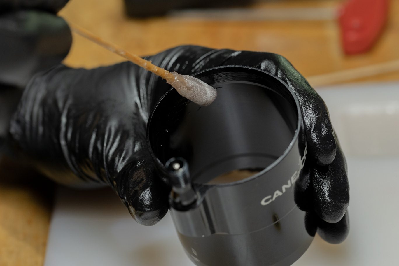
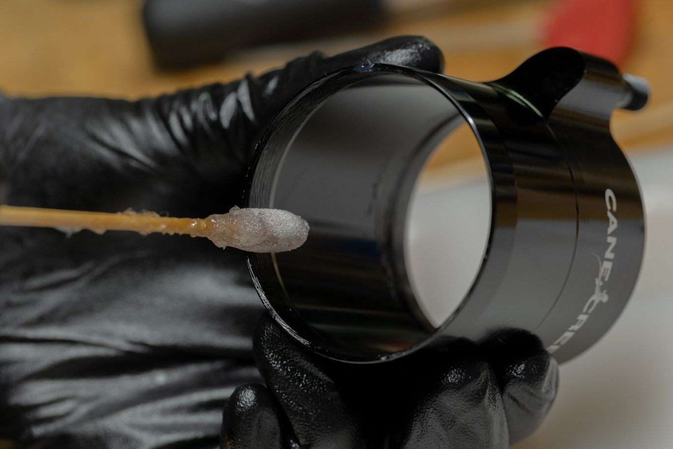
Step 2 – Inner Air Can Install
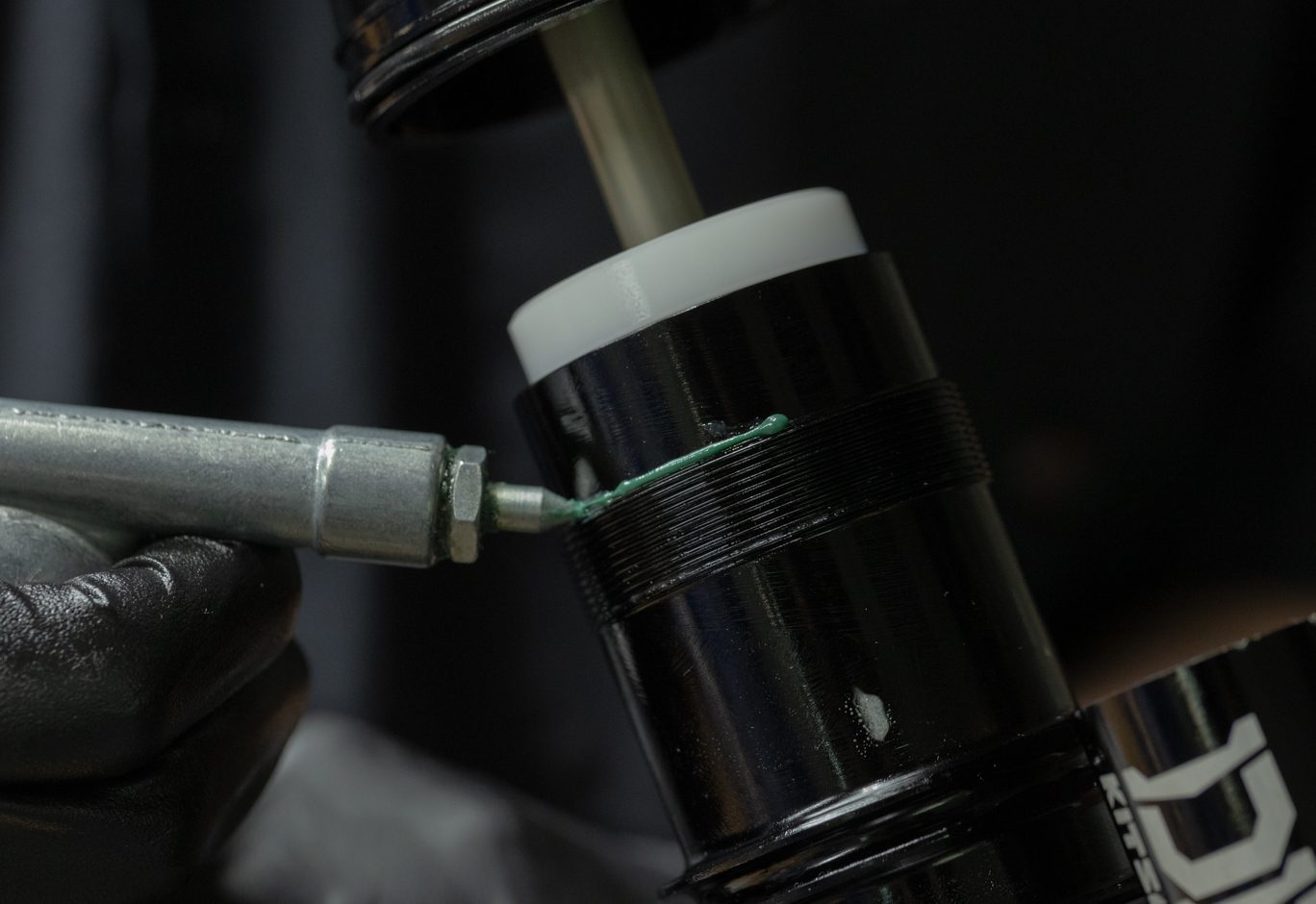
Lightly grease interior of inner air can between shelf and port hole. Lightly grease and install can retainer o-ring (AAD1102) on the topmost o-ring channel. Apply 2-4 cms of bicycle grease to the inner threads on the inner air can. Install inner air can past the air piston until it contacts air seal head.
Inner Air Can Prep
Inner Air Can O-Ring Install
Inner Air Can Threads Greased
Inner Air Can Install Past Air Piston
Inner Air Can Installed
Step 3 – End Eye Install
Lightly grease and install end eye can retaining o-ring (AAD1102) in topmost outer groove on end eye. Lightly grease and install shaft sealing o-ring (ACD0302) by gently working pass shaft threads until flush. Reinstall bottom out bumper and any stroke reduction needed. Apply blue Loctite (243) to threads on end eye and shaft. Thread end eye onto shaft. Insert 4mm Allen through end eye and torque end eye to 4.8 Nm using 1/2″ crowsfoot.
End Eye Can Retaining O-Ring Install
End Eye Can Shaft O-Ring Install
Working End Eye Can Shaft O-Ring Past Threads
Bottom Out Bumper Install
Bottom Out Bumper Installed
Stroke Reduction Install
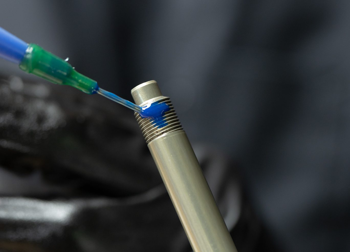
Loctite on End Eye
Loctite on Shaft
Attaching End Eye
Torquing End Eye on Shaft

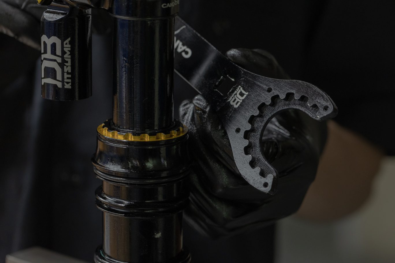
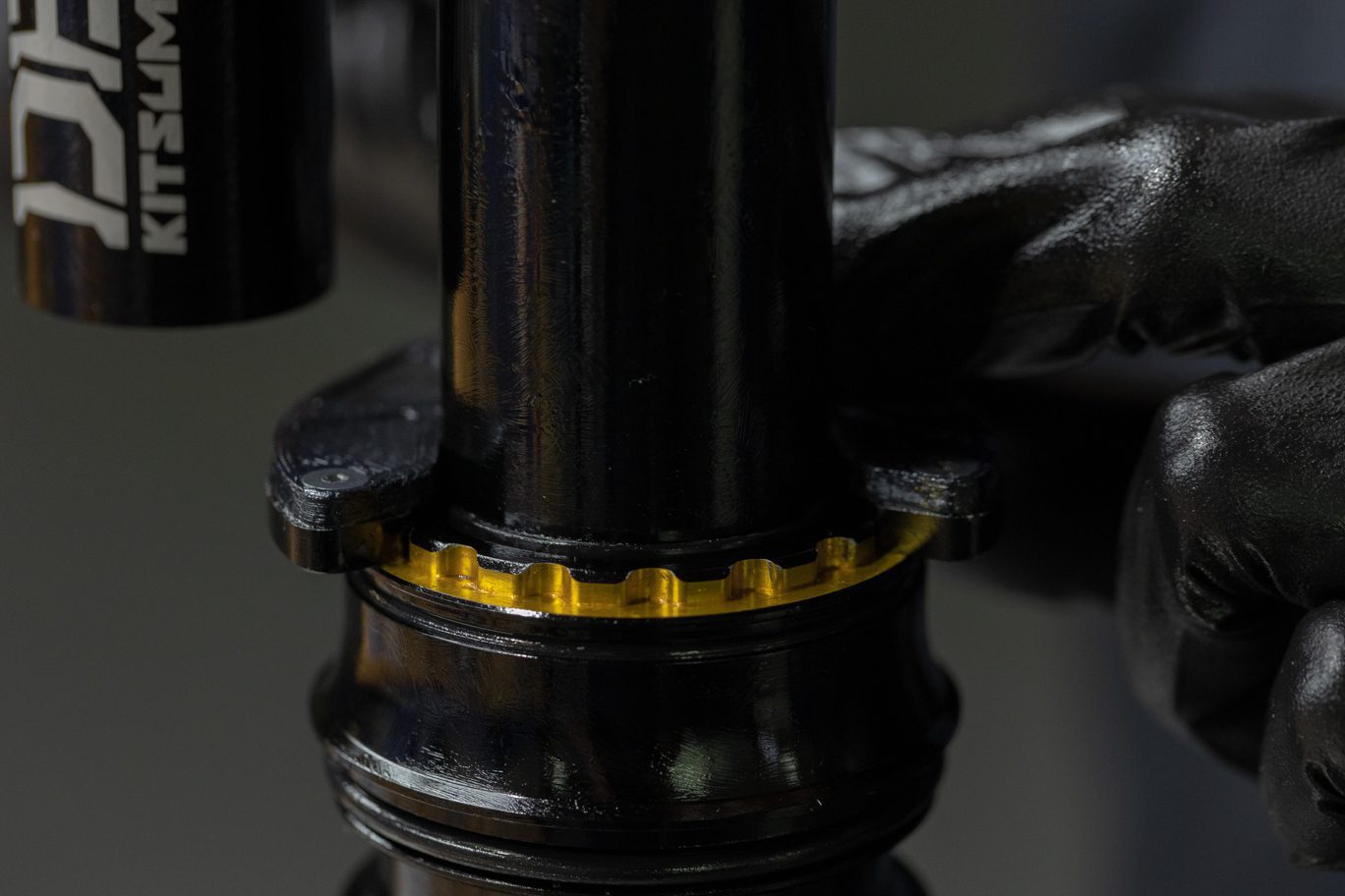
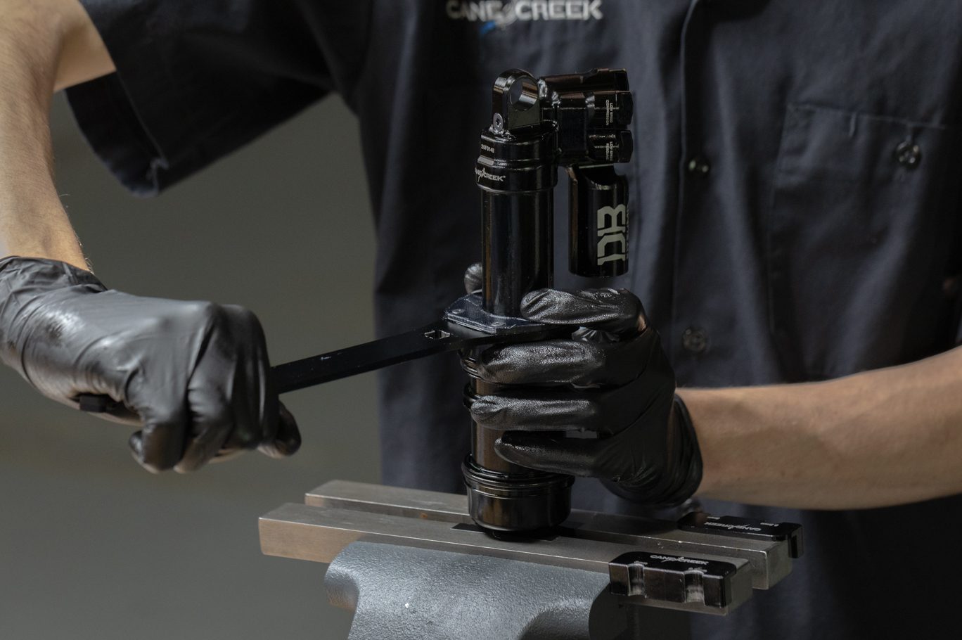
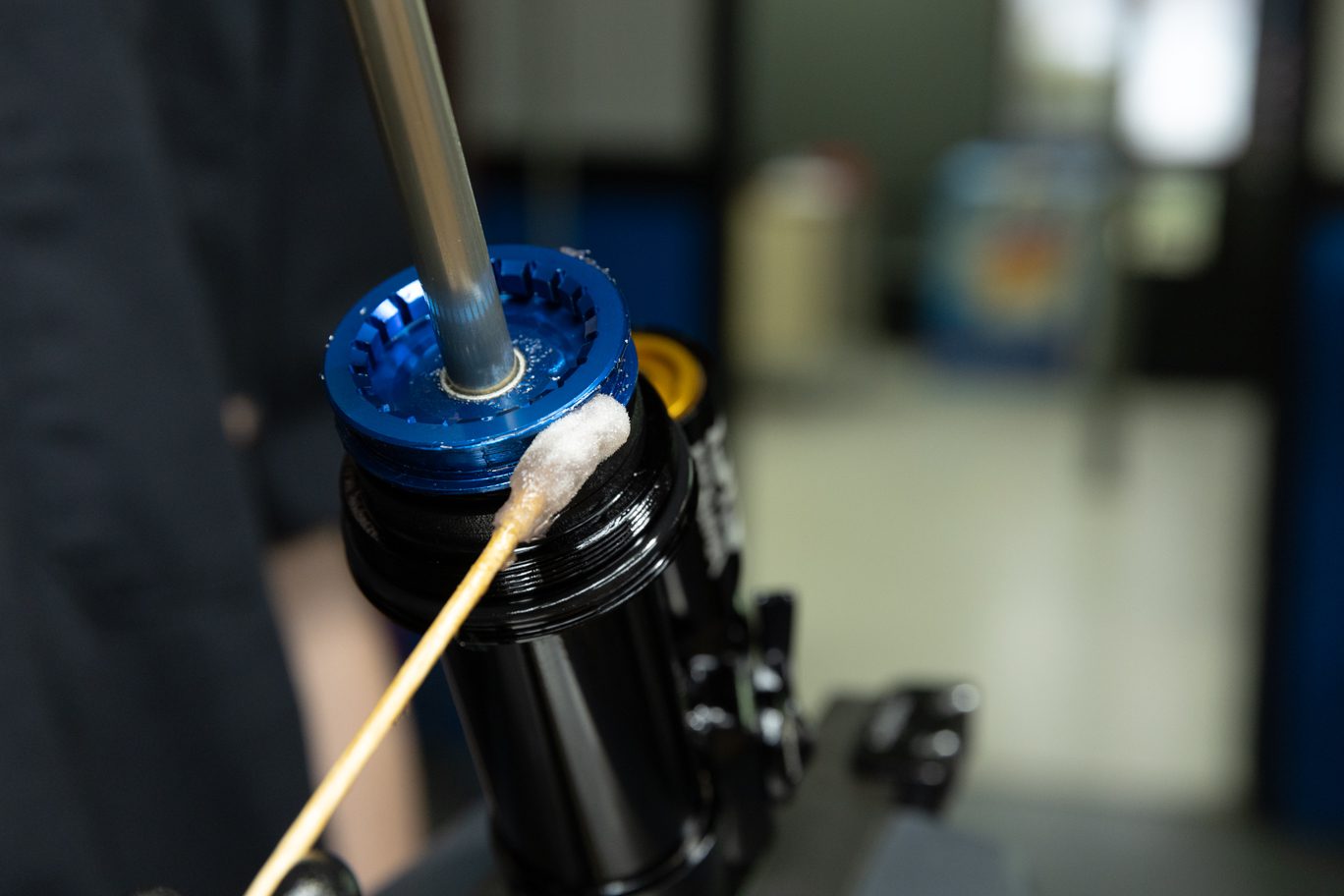
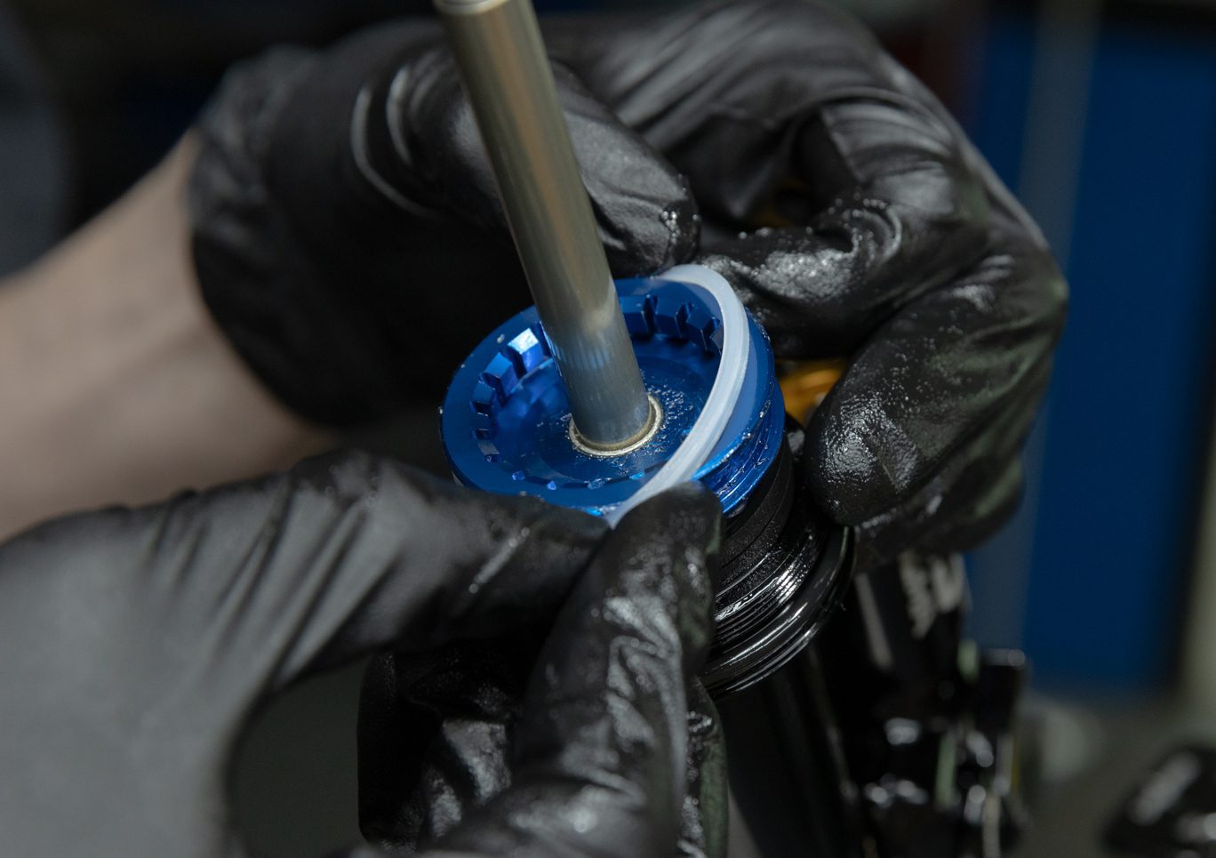
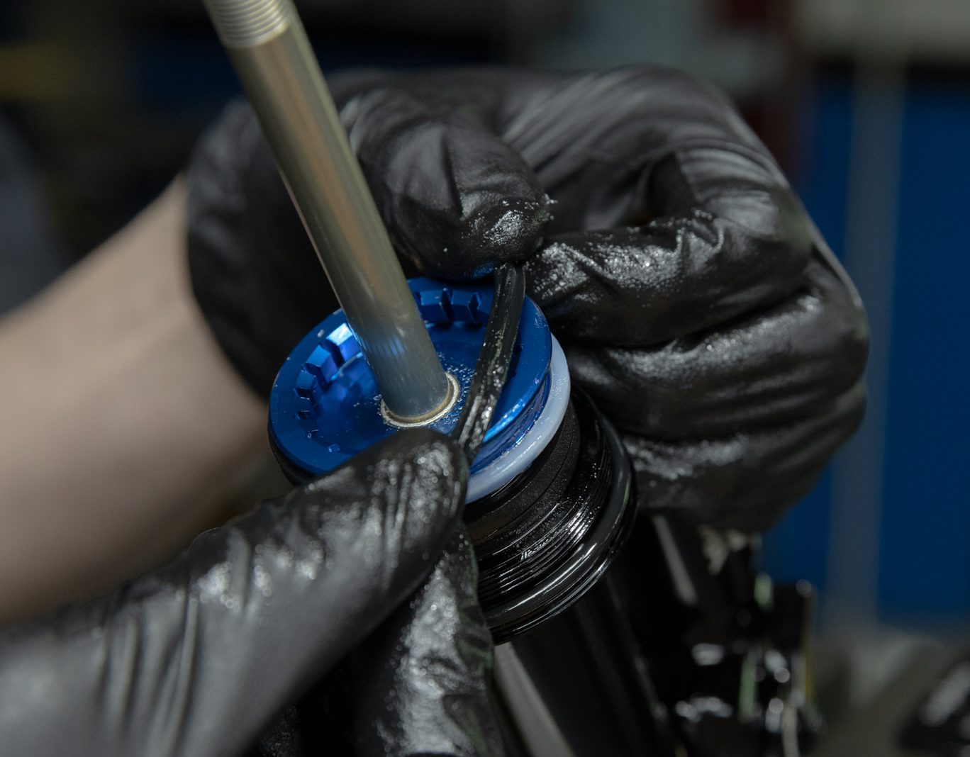
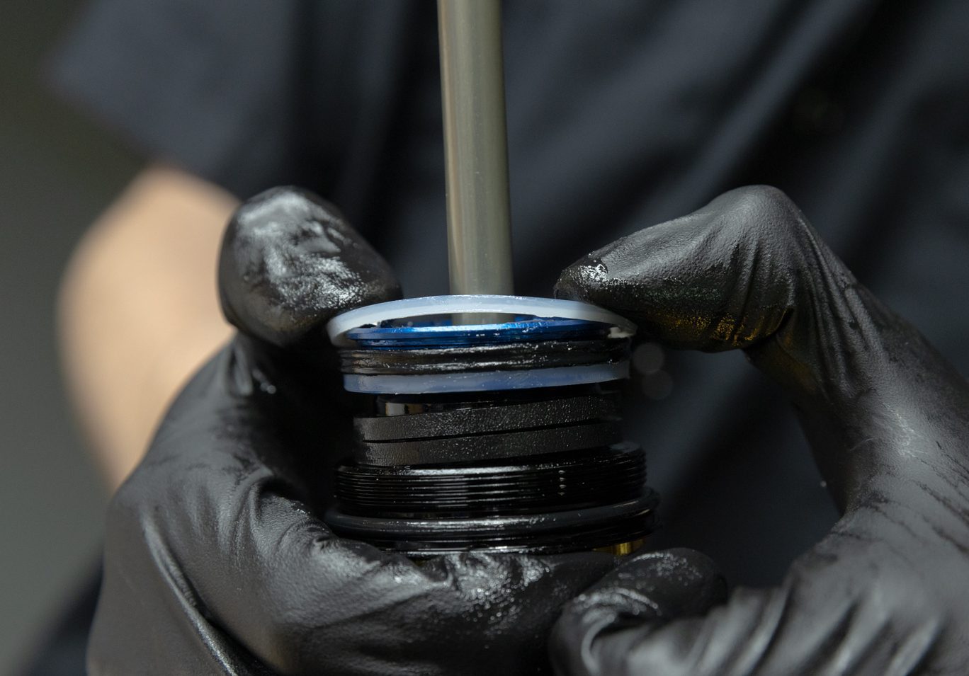
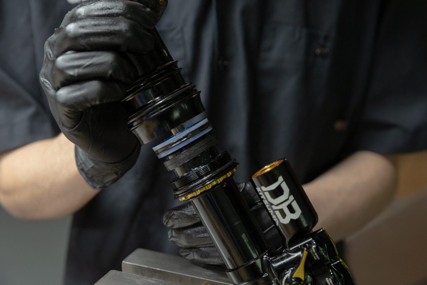
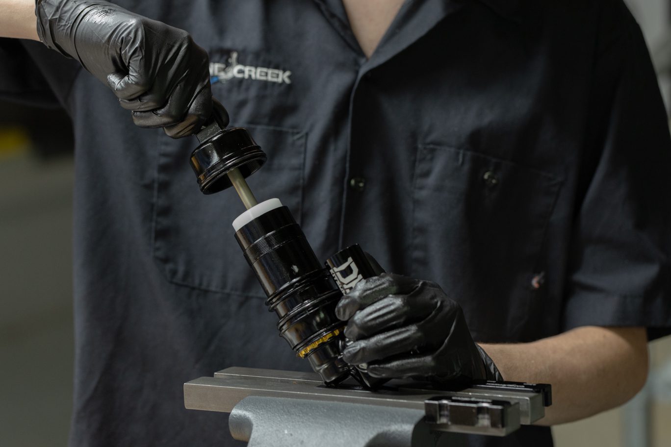
Step 4 – Air Seal Head/Inner Air Can/End Eye Install
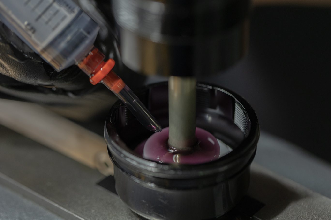
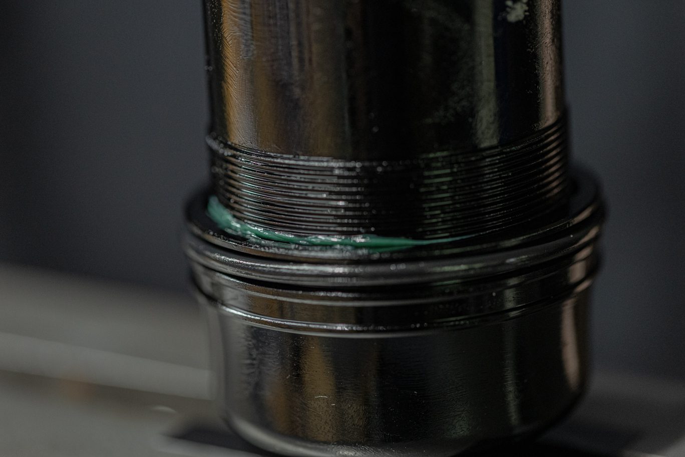
Apply 2-4 cms of bicycle grease to the outer threads on the inner air can. Flip shock in vise. Add 5 ml of Royal Purple to end eye. Hand thread inner air can onto end eye. Hand thread air seal head onto inner air can. Once both are hand tight, use Air Seal Head tool to tighten. Torque to 22.6 Nm.
Greasing Inner Air Can Threads
Adding Oil to End Eye
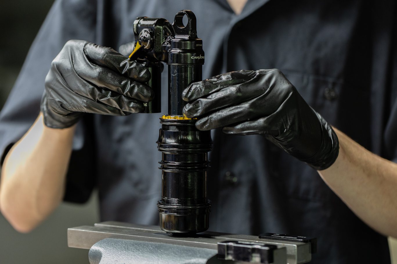
Threading Inner Air Can onto End Eye
Inner Air Can Threads Started
Inner Air Can Threaded on End Eye
Air Seal Head Threaded onto Inner Air Can
Air Seal Head Tool
Hand Tightening w/ Air Seal Head Tool
Tightening w/ Air Seal Head Tool
Torquing Air Seal Head/Inner Air Can/End Eye
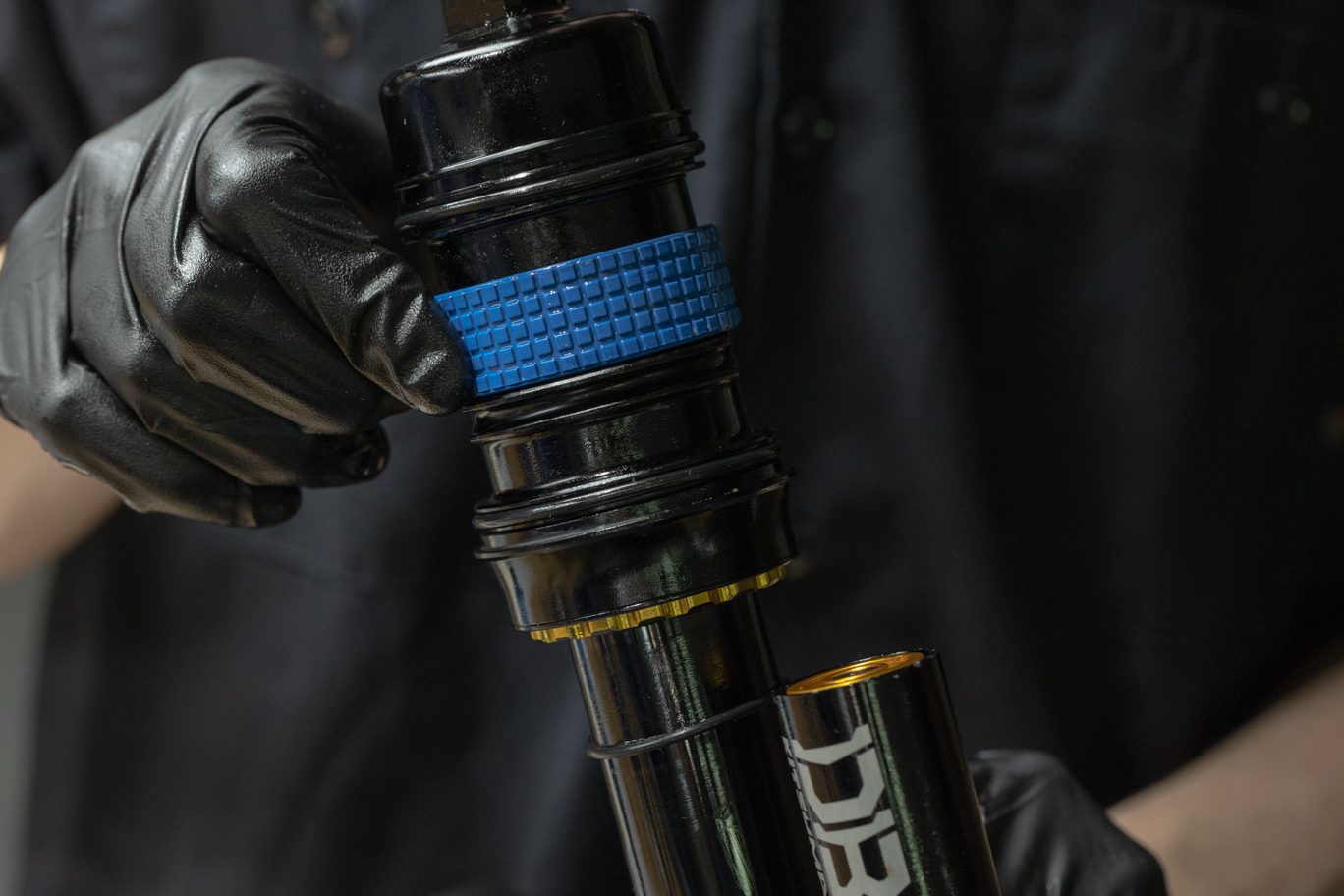
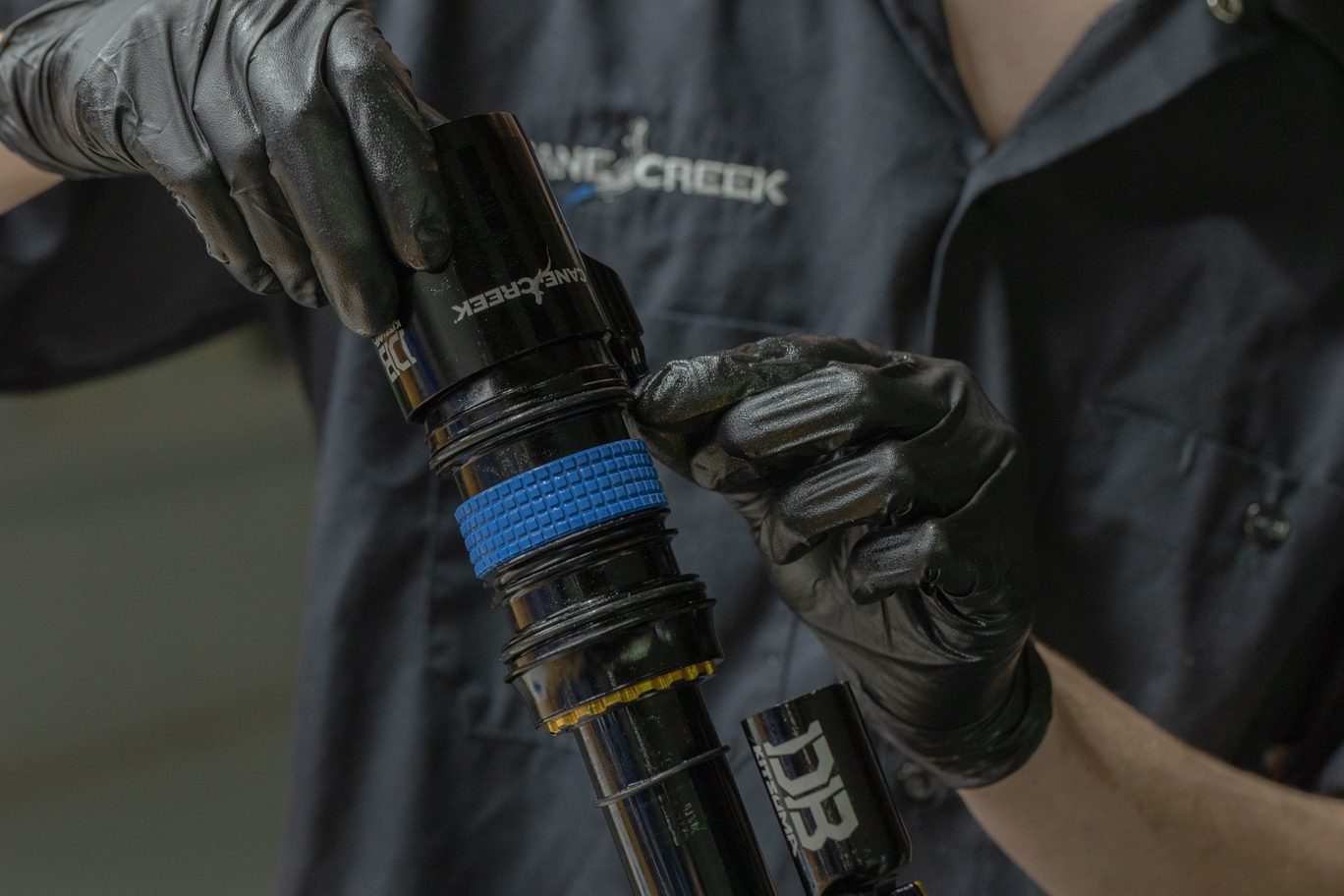
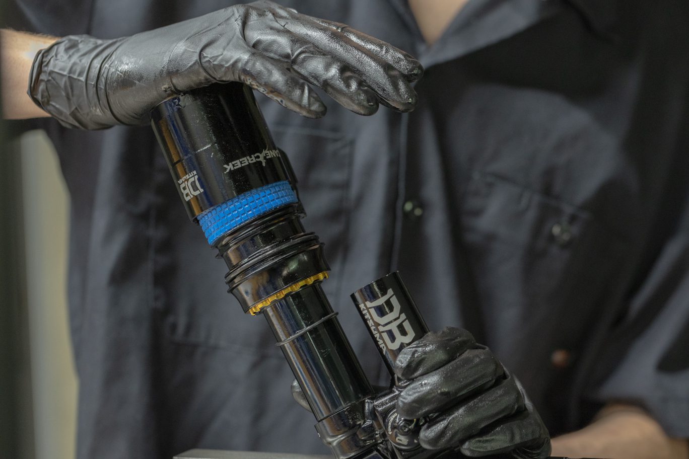
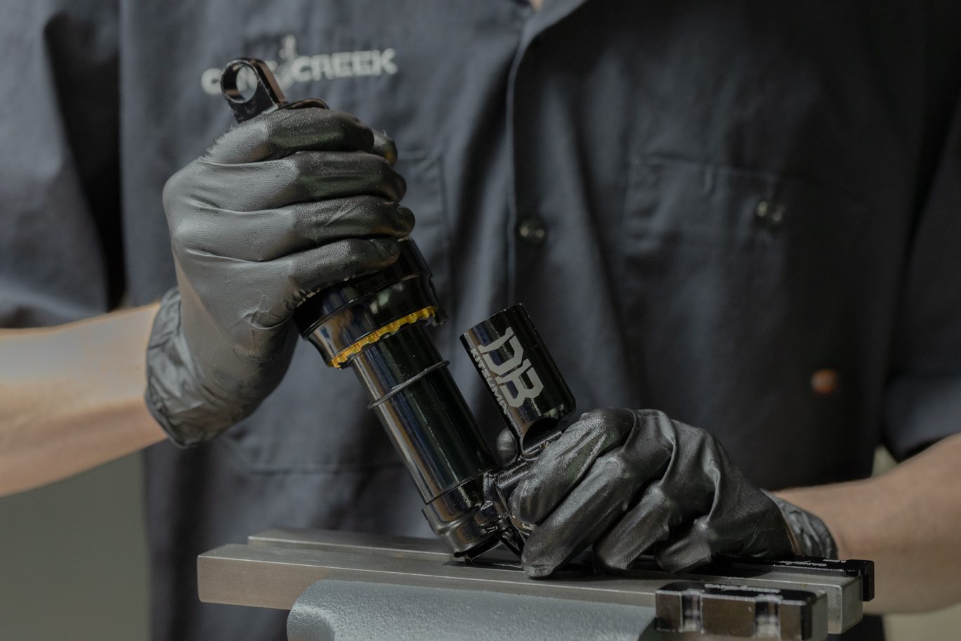
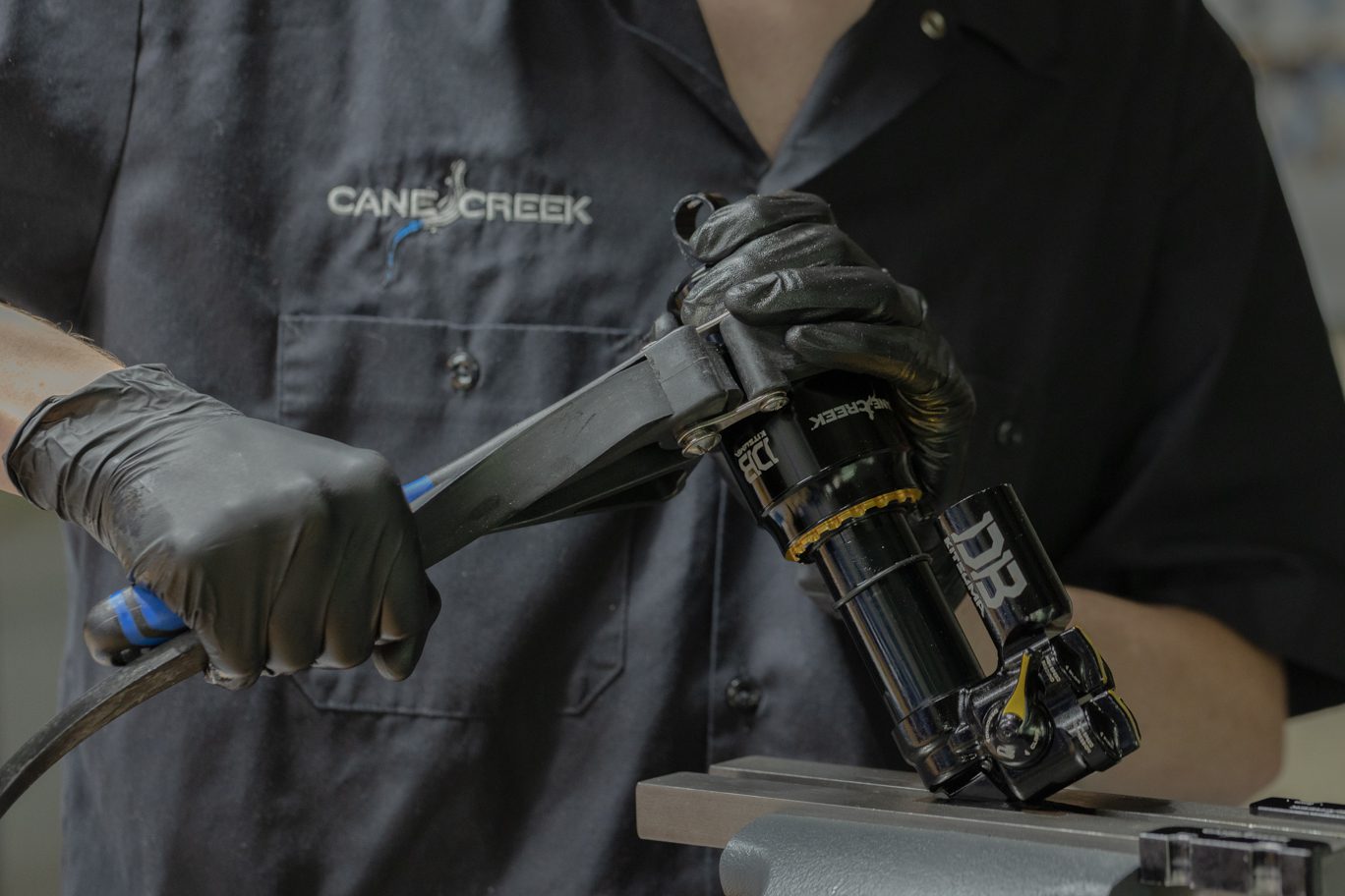
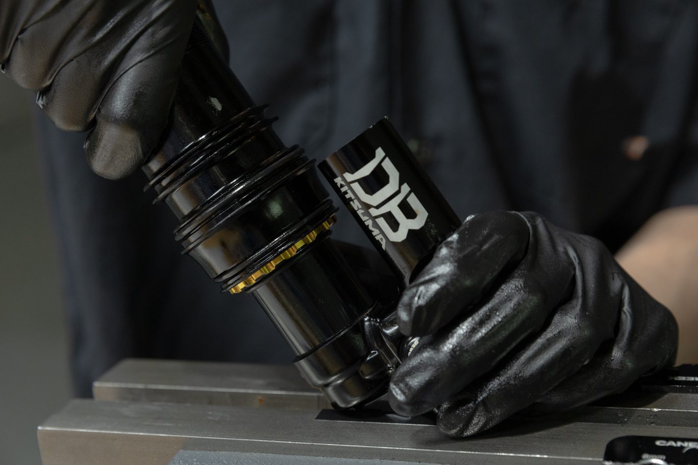
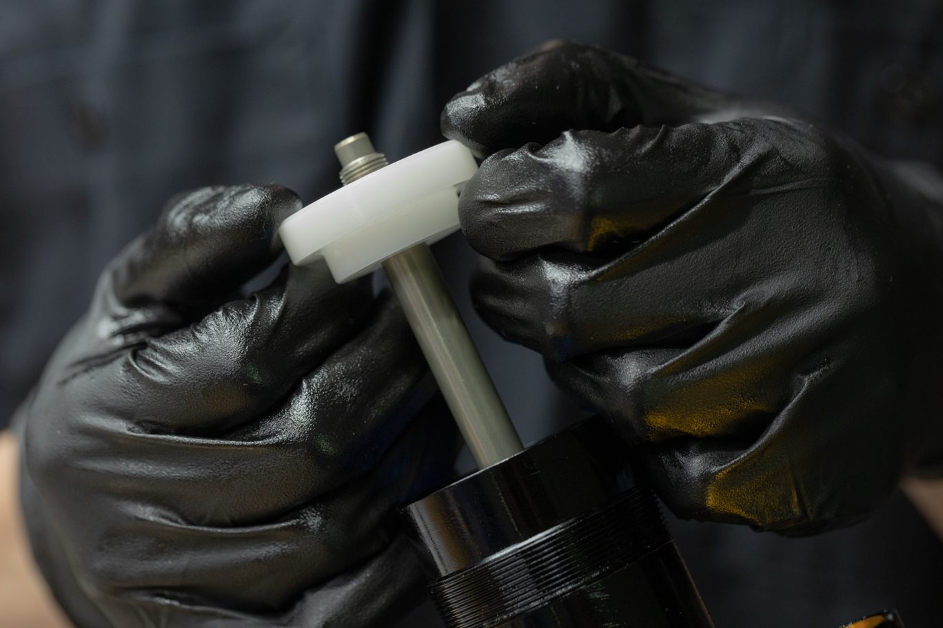
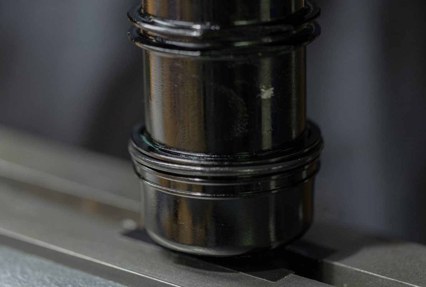
Step 5 – Outer Air Can Install
Lightly grease the interior ridges on the outer air can. Flip shock in vise. Install any volume reduction bands. Install air can with air valve towards cylinder head. Seating air can may require a strap wrench. Set desired air valve placement. Ensure air valve will not contact the reservoir tube at compression. Install dry air can retaining o-ring (AAD0012)
Outer Air Can Grease 1
Outer Air Can Grease 2
Volume Reduction Bands Installed
Starting Air Can Install
Air Can Install
Air Can Installed
Air Can Seating
Air Can Retainer O-Ring Install
Air Can Retainer O-Ring Installed
Final Testing and Set Up
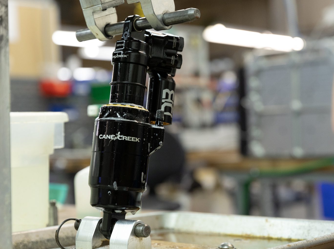
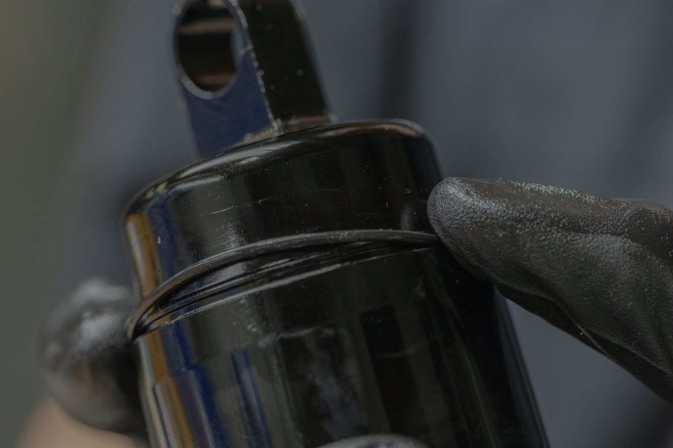
Step 1 – Leak Check
Air up shock to at least 100 psi. On hand dyno or bike frame, slowly cycle shock and listen for negative volume chamber to pressurize. Using soapy water and dunk tank, test for any possible air leaks. Install valve cap.
Airing Up Shock
Hand Dyno
Soap Leak Test
Water Leak Test
Valve Cap Install
Step 2 – Dyno Test
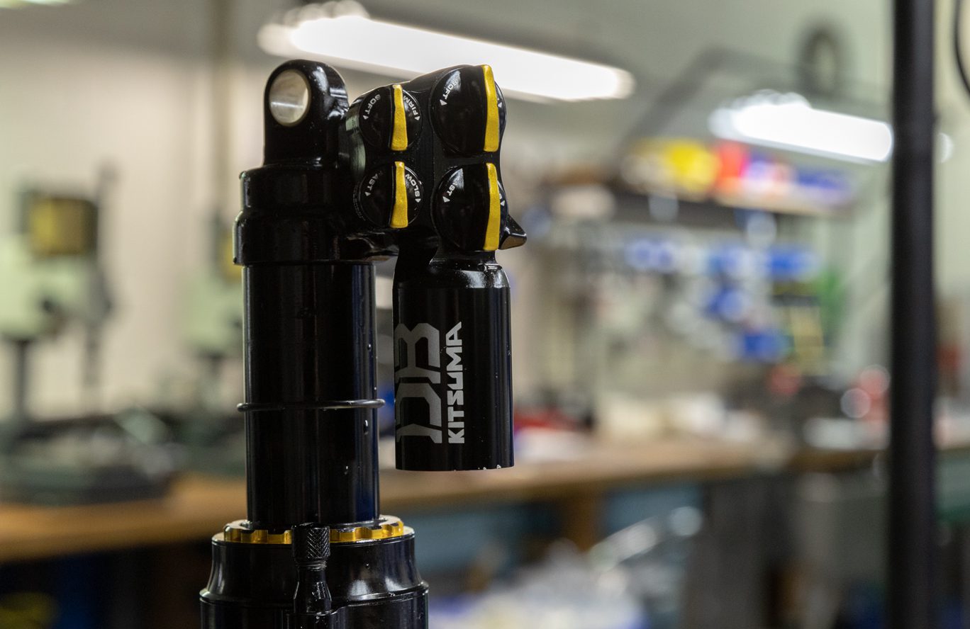
Set adjusters to factory neutral. Using hand dyno, test shock for function. Ensure Climb Switch engages and operates properly. Turn individual adjusters to test each one.
Install any bushings and hardware.
Factory Neutral