
DBcoil CS Complete 100 Hour Service Instructions (Part 2 of 3)
May 2022 orig., July 2022 rev.
Table of Contents
Recommendations and Warnings
Cane Creek recommends only trained suspension technicians perform service on all suspension, using all required tools and following all proper procedures. Anyone without access to the proper equipment or with any concerns on the procedures should defer to an authorized Cane Creek service center for service. Improper service can result in loss of performance or suspension failure. All Cane Creek shocks have pressurized nitrogen and oil, even coil shocks. Follow the service procedures exactly as written to avoid possible injury or harm to the suspension. Always wear eye protection while performing suspension service.
Please dispose of all waste products and materials through proper channels to avoid contamination of the environment.
Any damage or issues resulting from improper service will not be covered by warranty. If you have a shock still in its original warranty period and do not wish to void your warranty, please contact an authorized Cane Creek service center.
These service instructions cover the basic service procedures using standard service kits. If your suspension requires parts beyond standard replacement parts – shaft, damper tubes, end eyes – please consult your authorized Cane Creek service center or contact us at our Cane Creek Support Center.
Service Notes
The DBair CS and Coil CS share many service steps. Additionally, the Standard and Trunnion variants of both models have identical service procedures other than where to clamp the cylinder head. Some images in these instructions may not be identical to the valve body or outer damper tube on the Coil CS, but process is the same for the shock in the image and the shock on your bench.
Additionally, running changes happened throughout the lifespan of the Coil CS. Many of those are addressed in the Technical Service Bulletins below, but always take note of the way the shock is originally built and replicate that during reassembly to maintain the original performance, tune, set up, etc.
8mm Shafts
In 2018, all Coil CS shocks transitioned from 8mm to 9.5mm shafts to be more compatible with modern higher leverage ratio bikes. Factory service support is no longer available for 8mm shafts outside of 9.5mm shaft upgrade kits. If you are interested in maintaining an 8mm shaft on a shock, please consult your authorized Cane Creek service center.
Service Kits
BAD2376 – DBcoil CS Complete Rebuild Kit
If 8mm shaft present, ONE of the following 9.5mm shaft upgrade kits is required (plus any stroke reduction clips needed from full stroke):
BAD1599 – 9.5mm Shaft Assembly – 200x57mm
BAD1600 – 9.5mm Shaft Assembly – 216x63mm
BAD1601 – 9.5mm Shaft Assembly – 222x70mm
BAD2322 – 9.5mm Shaft Assembly – 230x70mm
BAD0356 – 9.5mm Shaft Assembly – 240x76mm
BAD1603 – 9.5mm Shaft Assembly – 267x90mm
Required Cane Creek Tools
DBT018 – DB Seal Head Pin Spanner Wrench
AAD1361-01 – DBCoil/ DBAir – Oil Fill Needle Adapter
DBT016 – DB Gas Fill Needle
AAD0555 – 8mm & 9.5mm Shaft Clamp
AAD0756 – DB Valve Seat Tool
BAD1298 – DBcoil Seal Head Bullet
DBT012 – DB IFP Setting Tool
Additional Tools & Supplies
Allen wrenches – 1.5 & 3mm
Torx wrenches – T20
Sockets – 13mm
Crowfoot wrenches – 1/2″
9.5mm Shaft Bullet
Torque wrenches
Pick
Pin Spanner
Needle Nose Pliers
Strap wrench
Suspension Grease
PolyLube Grease
Motorex 4wt Racing Fork Oil
Vacuum Oil Fill Machine
Nitrogen Fill System
Torque, Loctite, Oil & Nitrogen Specs
Torque & Loctite Chart
| Part | Torque Spec | Loctite Spec |
|---|---|---|
| Shaft Nut | 13.5 Nm | 243 (Blue) |
| Climb Switch Plate Cover | 0.16 Nm | 243 (Blue) |
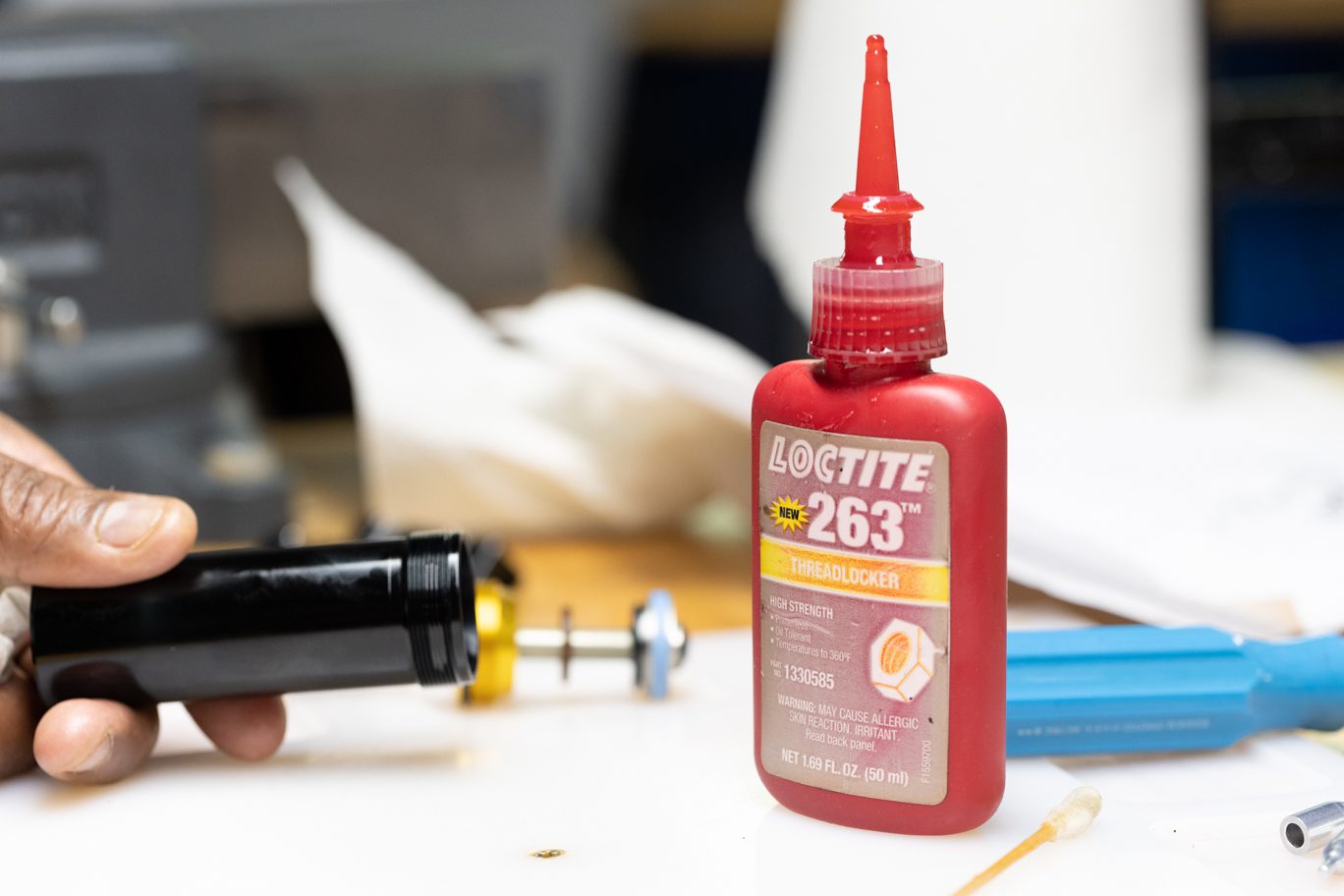
| Outer Damper Tube | Tight | 263 (Red) |
| Valve Seat | 4.8 Nm | None |
| Climb Switch Screw | 1.2 Nm | 243 (Blue) |
| Oil Seal Head | 15 Nm | None |
Oil Chart
| Oil Location | Oil Type | Oil Amount |
|---|---|---|
| Damper Fill | Motorex 4wt Racing Fork Oil | Fill to 3 Bars |
Nitrogen Chart
| Nitrogen Location | Nitrogen Pressure |
|---|---|
| Valve Body | 11 - 12 Bars |
Shaft Disassembly


Step 1 – Piston Assembly Removal
****If replacing an 8mm shaft with a complete 9.5mm shaft assembly, this step section can be skipped and the complete 8mm shaft assembly can be discarded.****
Using shaft clamp, secure shaft between end eye and bottom out bumper. Using 13mm socket, remove shaft locknut. Remove piston, shims and stop washer, noting orientation. Some Coil CS shocks use a single sided Air CS shim stack.
TSB034 – DBcoil CS Oil Piston Change
Shaft Clamped for Disassembly
Freeing Shaft Nut
Shaft Nut Removal
Piston, Shim Stack and Stop Washer Removed


Step 2 – Shim & Piston Inspection
Check face shim for port wear and flip on reinstall if necessary. Check ports on piston for excessive wear. If present, resurfacing or replacement of piston may be necessary.
Locknut, Piston, Shim Stack & Stop Washer Removed
Inspecting Shim Face


Step 3 – Final Disassembly
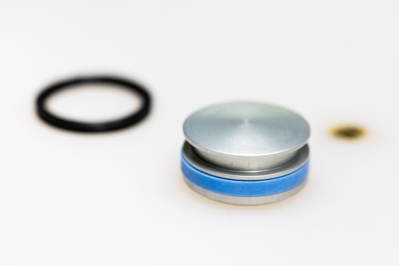
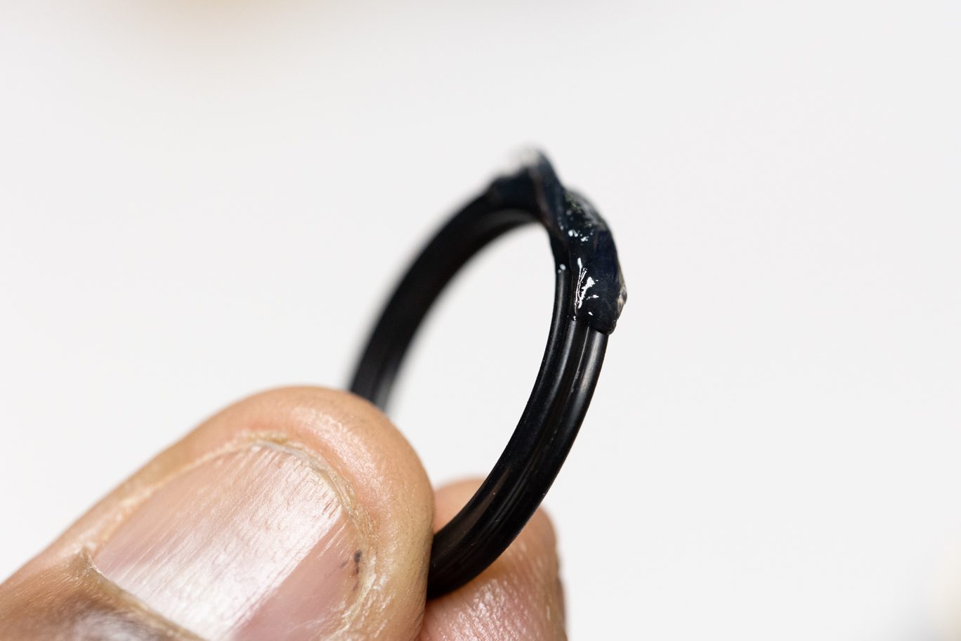
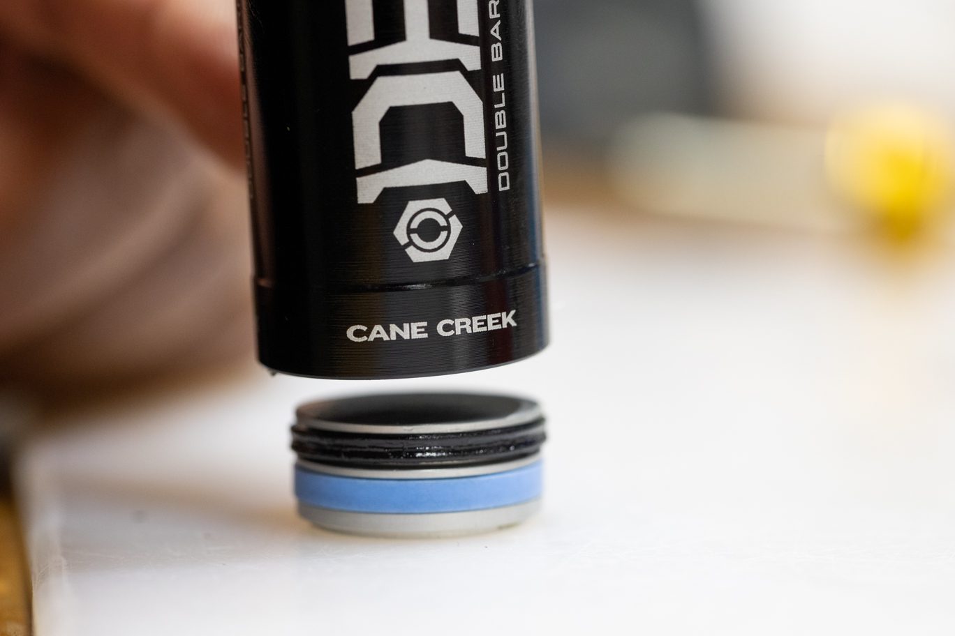
Remove and discard top out bumper and oil seal head. Remove bottom out bumper.
Top Out Bumper & Oil Seal Head
Top Out Bumper & Oil Seal Head Removed
Bottom Out Bumper Removed
Shaft Reassembly


Step 1 – Oil Seal Head Install
****If replacing an 8mm shaft with a complete 9.5mm shaft assembly, this step section can be skipped. The replacement 9.5 shaft assembly comes ready for installation.****
Using 9.5mm shaft bullet, install bottom out bump, new oil seal (AAD0355), and new top out bumper (AAD1090).
Shaft Bullet on Shaft
Bottom Out Bumper Installed
Oil Seal Head Installed
Top Out Bumper Installed


Step 2 – Shim Stack & Piston Install
Remove bullet and install stop washer, shims and piston. Note shim stack orientation. Flip face shim if needed. Apply blue (243) Loctite to threads of locknut. Install and torque shaft locknut to 14.5 Nm using 13mm socket.
TSB034 – DBcoil CS Oil Piston Change
Stop Washer Installed
Lower Shim Stack & Piston Installed
Upper Shim Stack Installed
Apply Loctite to Shaft Locknut
Torquing Shaft Nut
Damper Reassembly


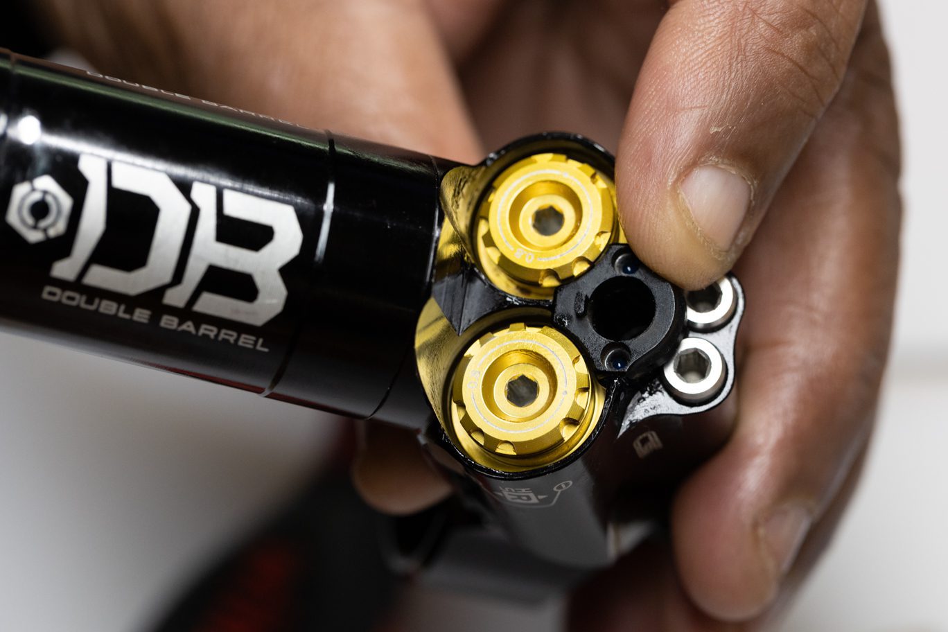
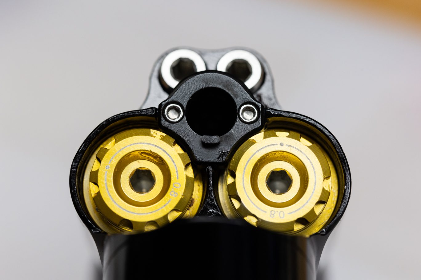
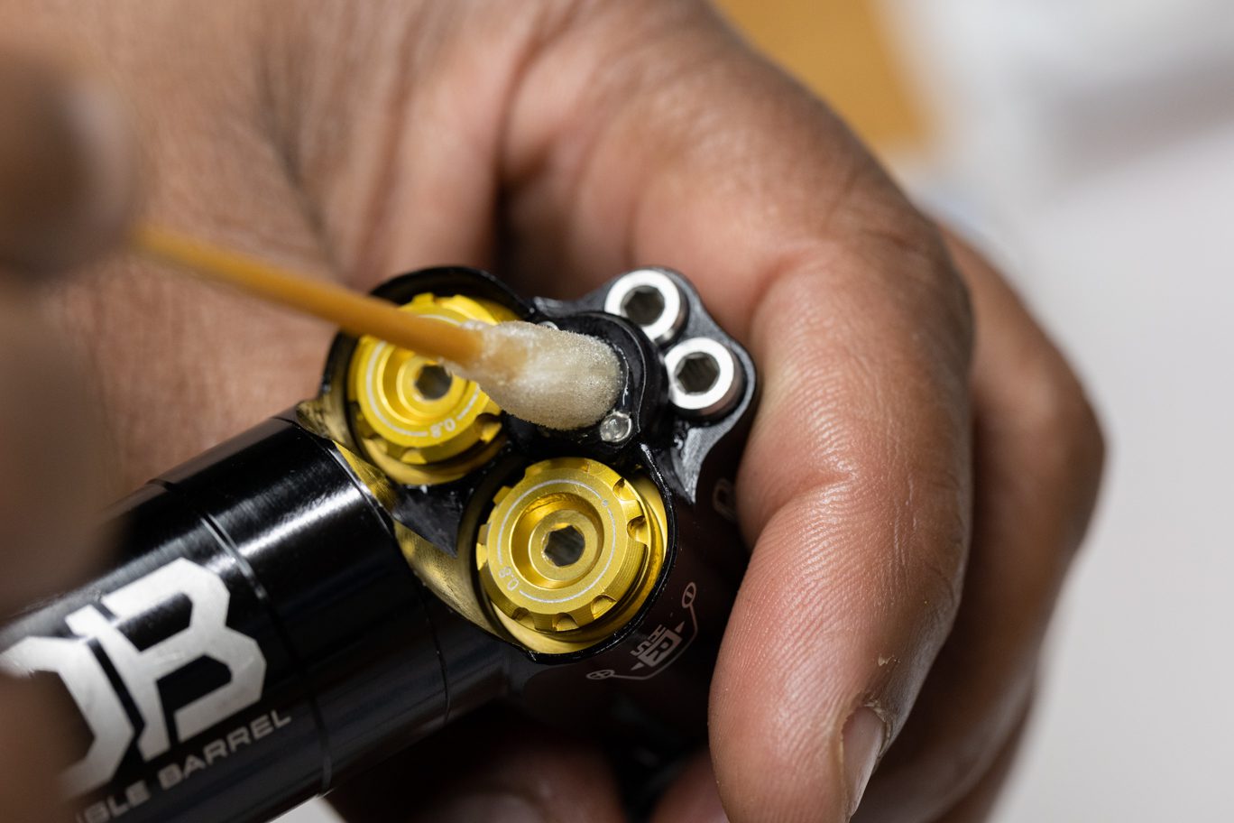
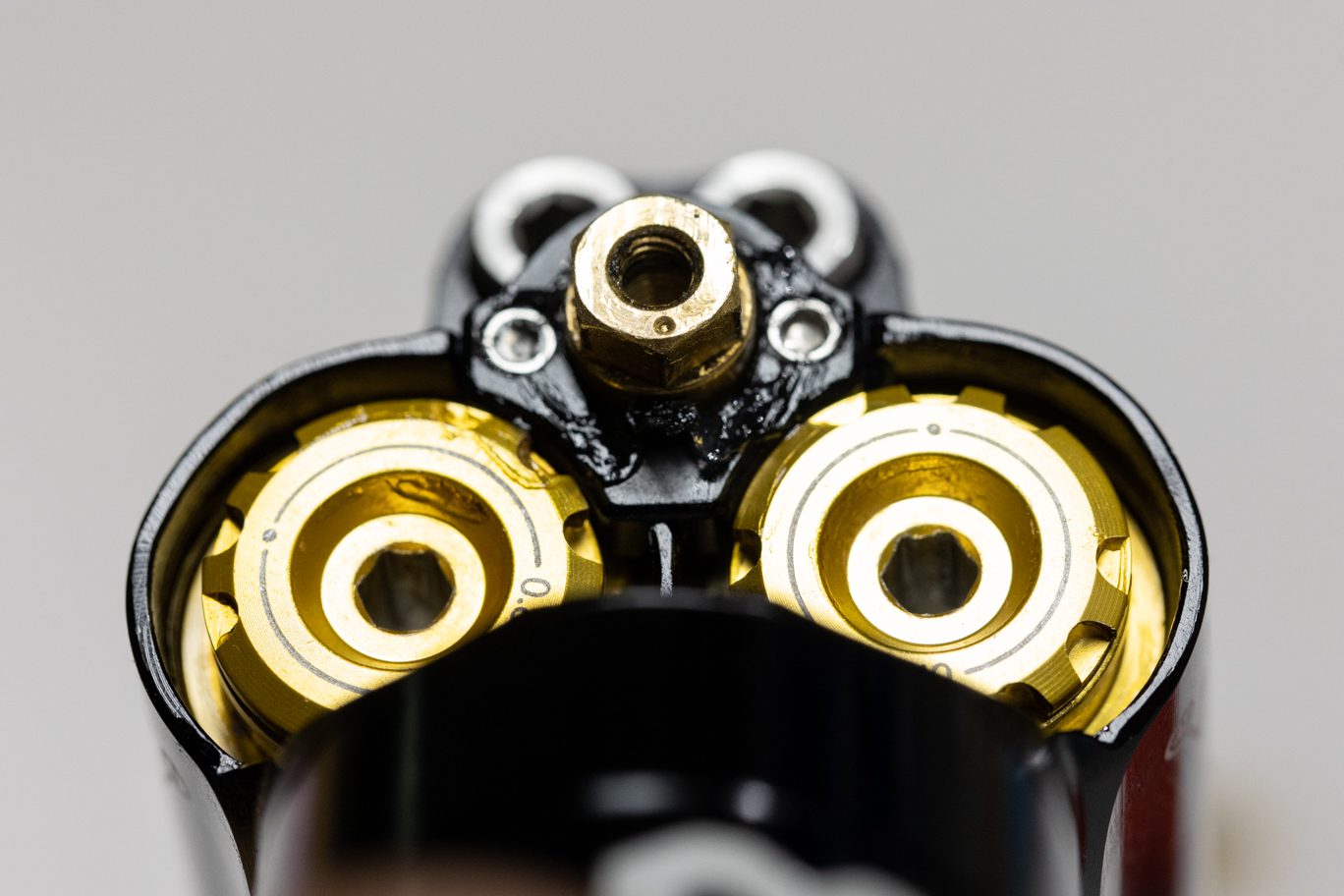
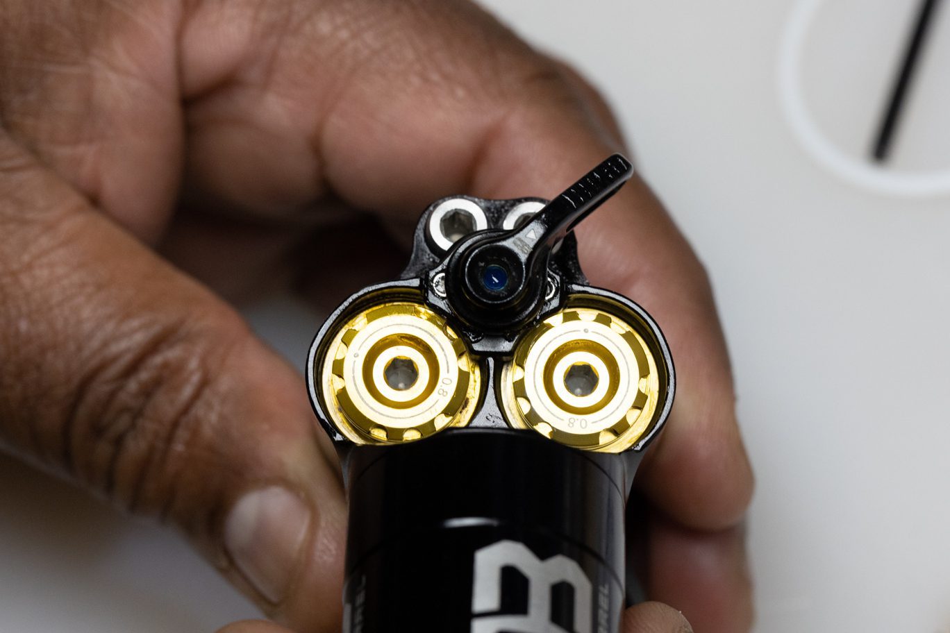
Step 1 – High Speed Adjuster Prep
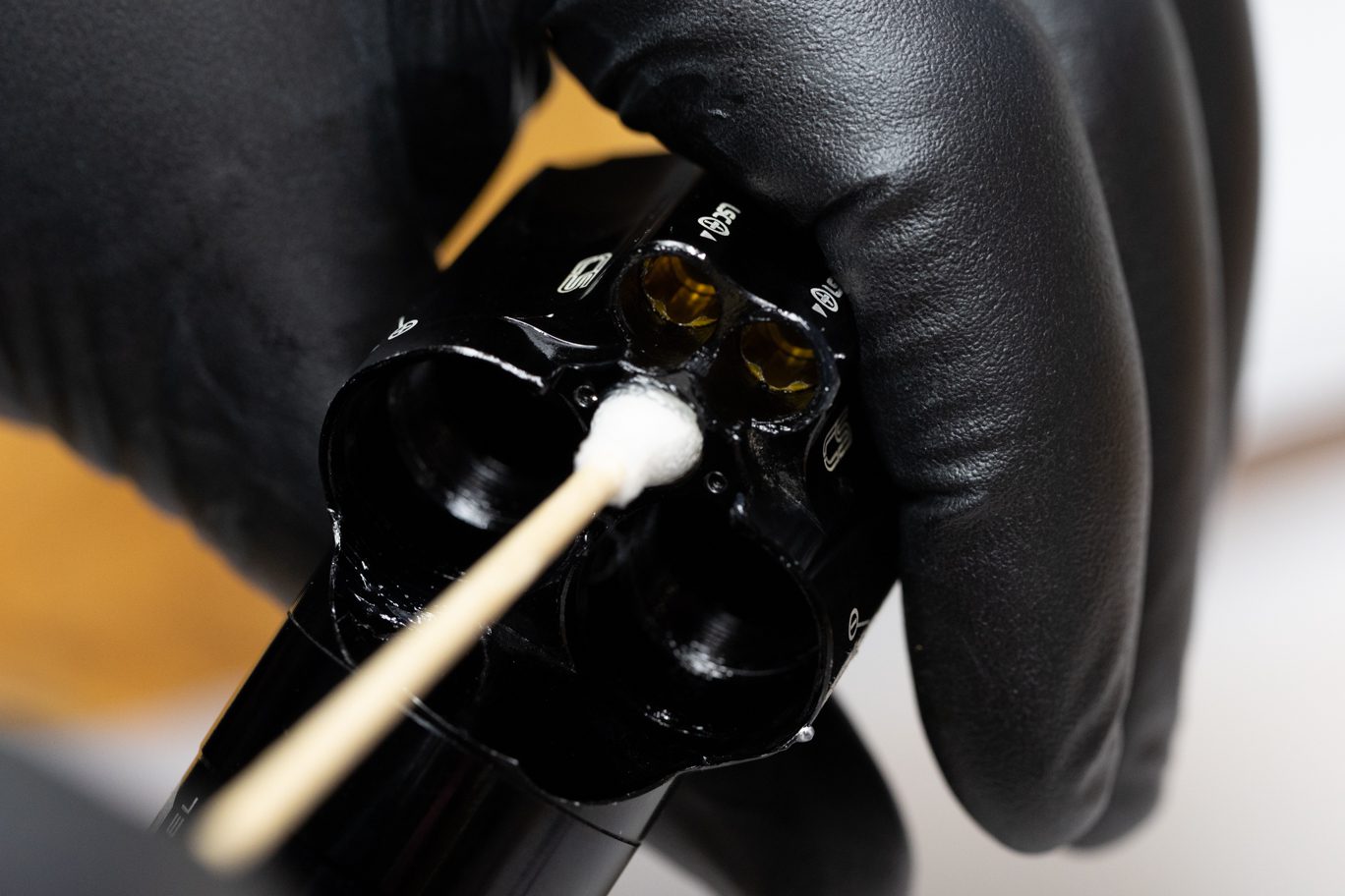
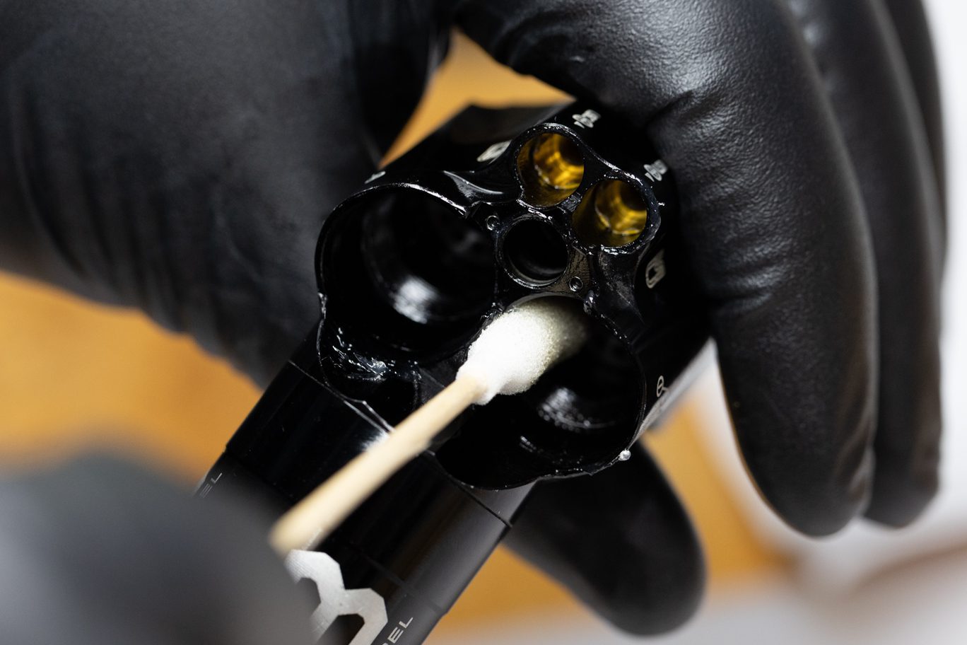
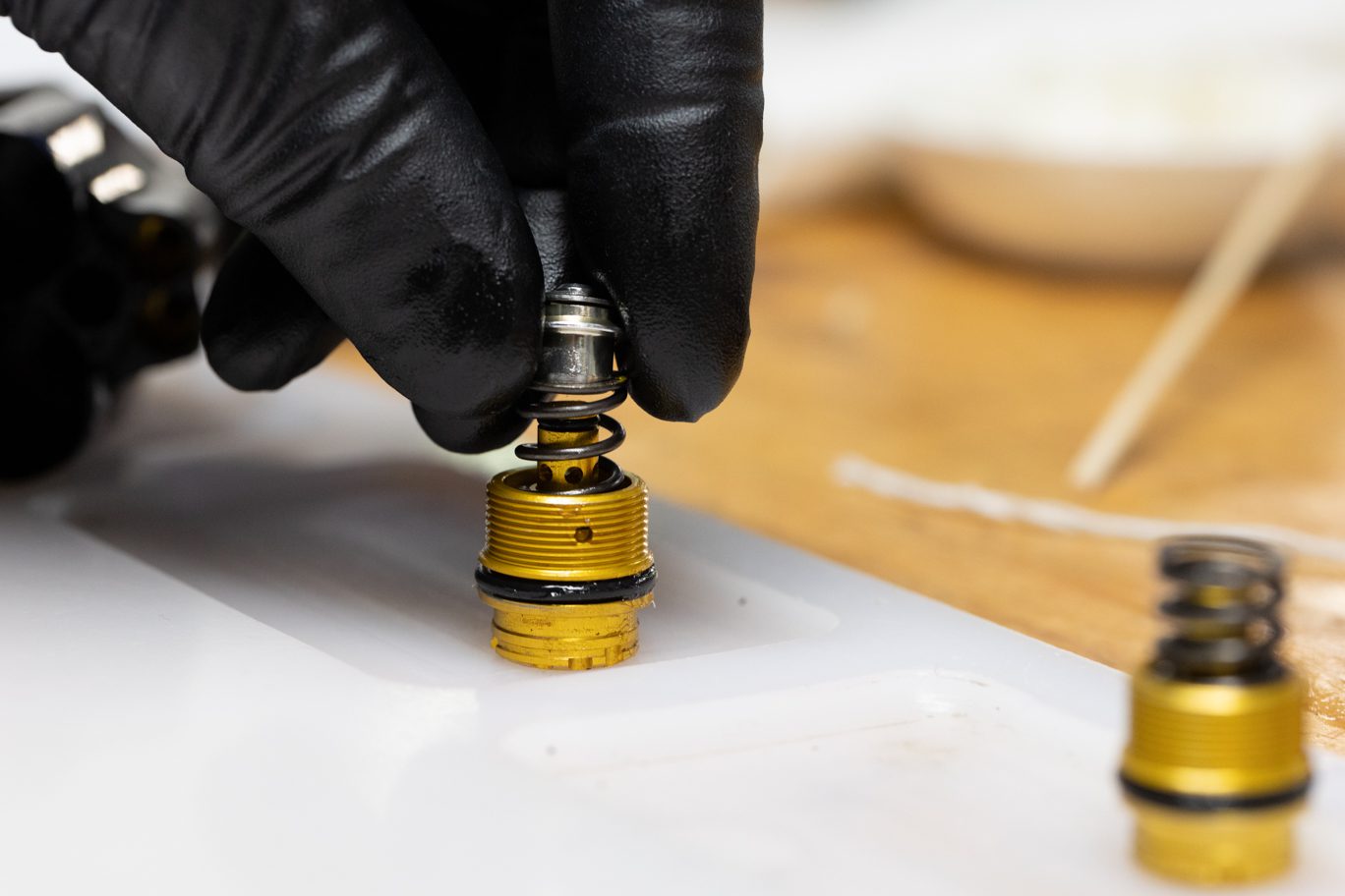
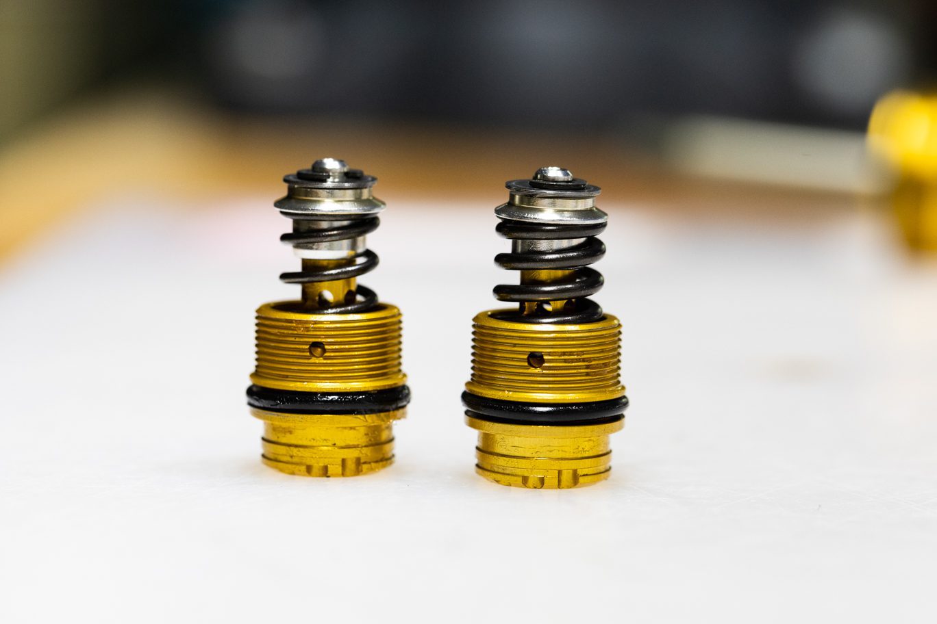
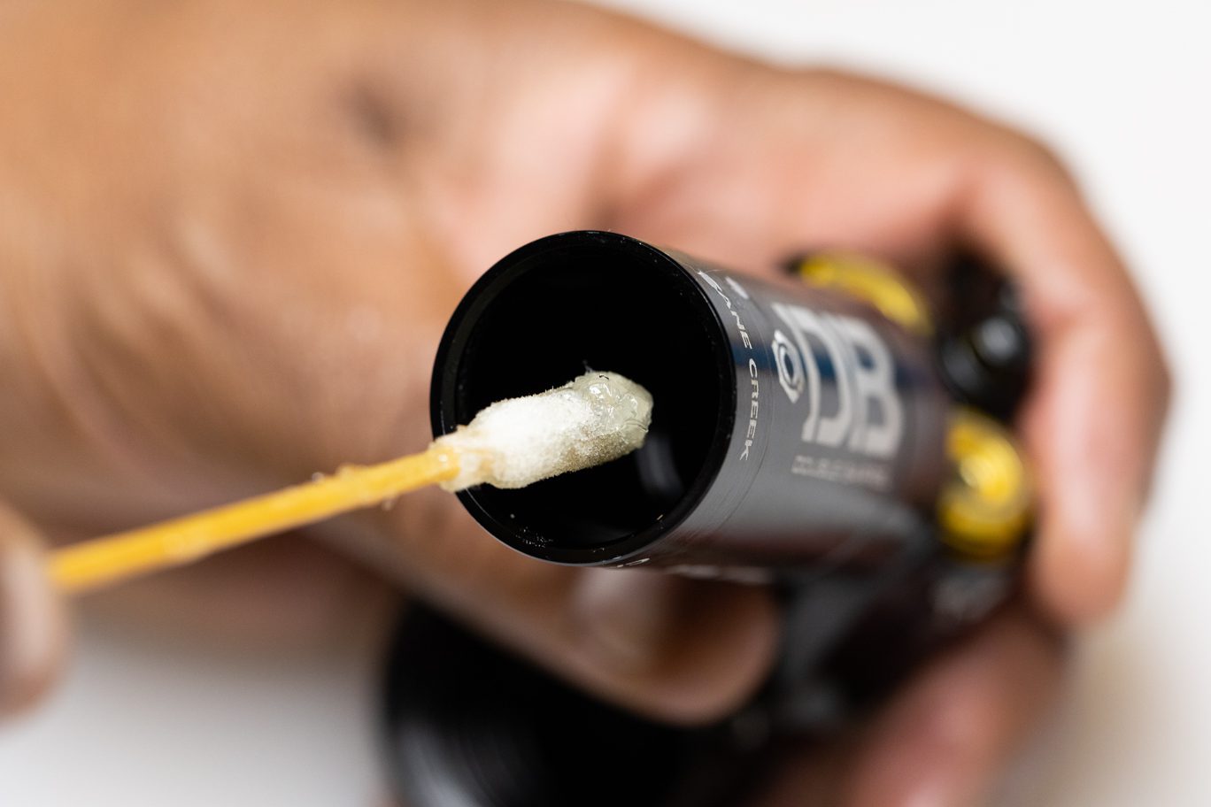
Lightly grease the walls of the spool valve and adjuster housing on valve body. Lightly grease and install high speed adjuster outside o-ring (AAD0032). Install high speed adjuster poppet o-ring (.DB11101). Install spring and poppet on high speed adjuster.
Replicate the original set up from disassembly. Rebound adjuster (0.8 with port) and spring (red, 30wt weight) and Compression adjuster (will vary from 0.0 without port, to 0.8, 1.0 or 1.2 with port) and spring (yellow, 10wt or standard 20wt). Spring color may have worn off.
Greasing Climb Switch Spool Valve Housing
Greasing High Speed Valve Housings
Greasing Low Speed Valve Housings
High Speed Adjuster Poppet O-Ring Installed
High Speed Adjuster Outside O-Ring Installed
High Speed Adjuster O-Rings Installed
High Speed Adjuster Spring & Poppet Install
High Speed Adjuster Spring & Poppet Installed
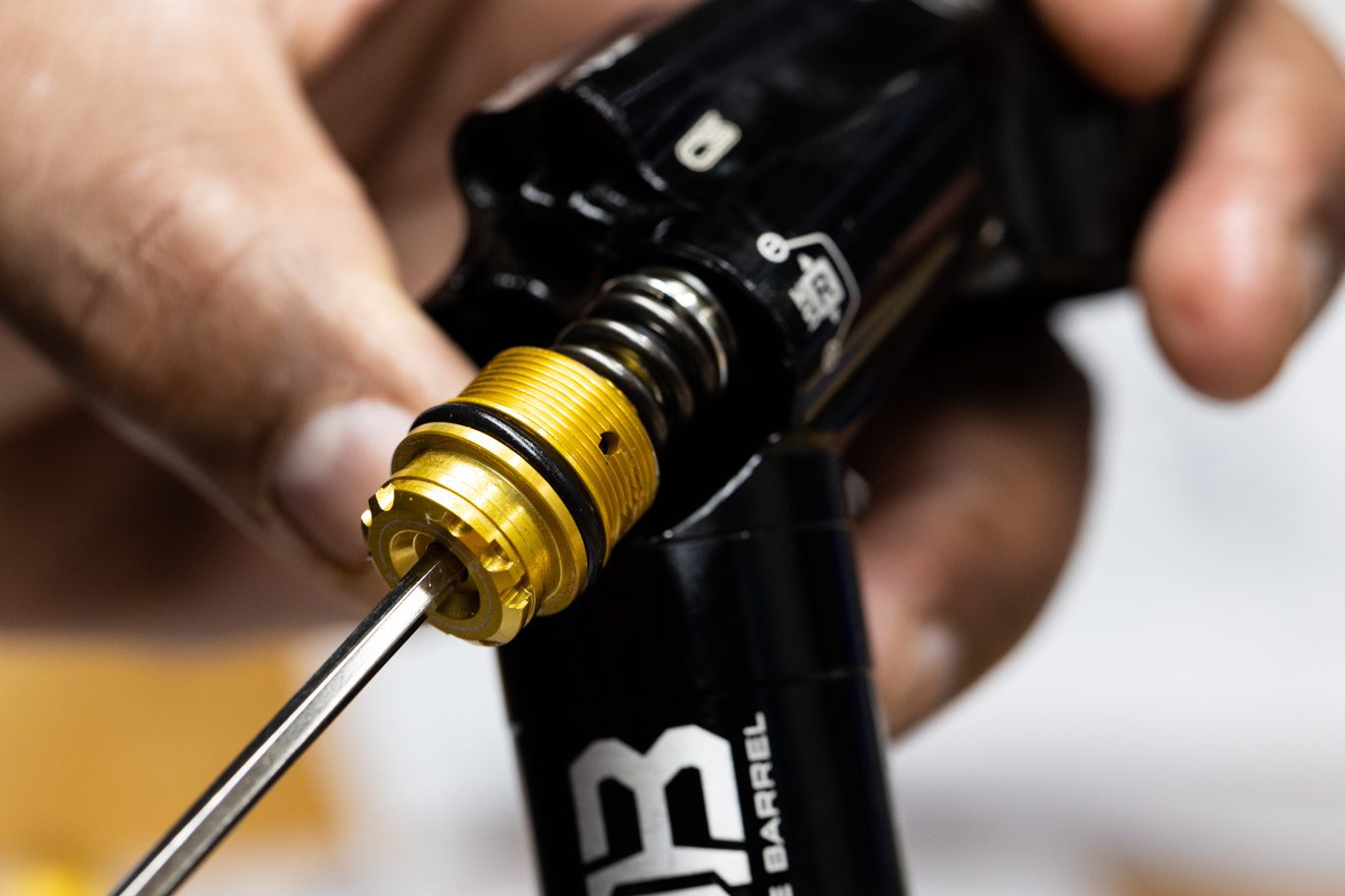
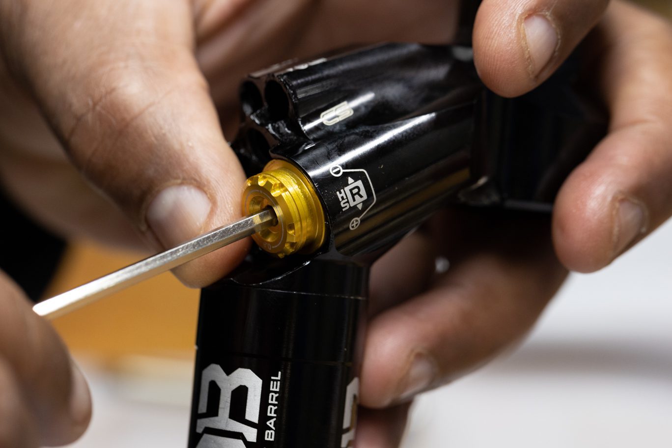
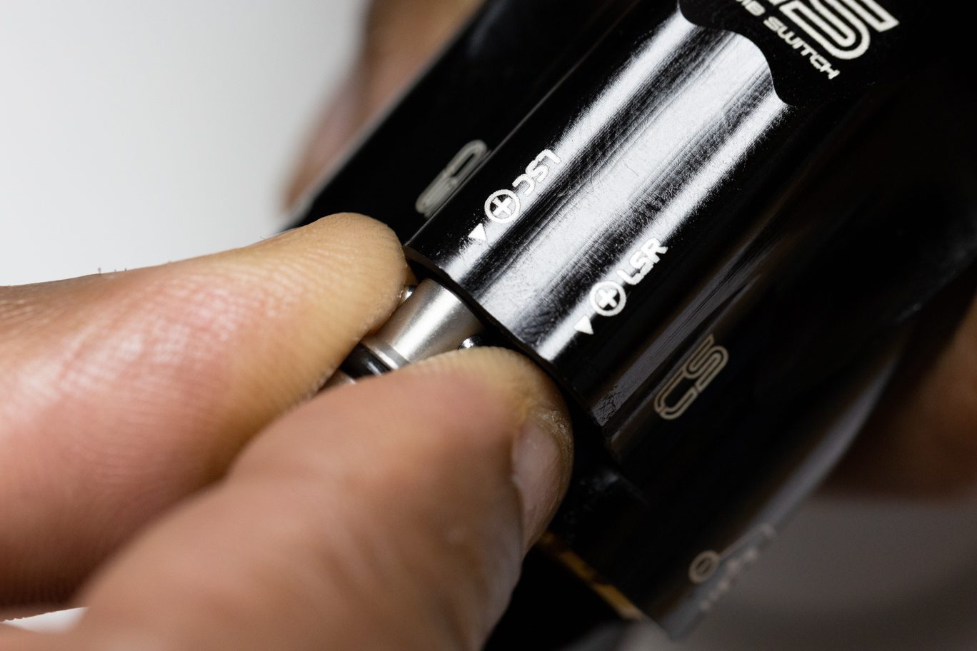
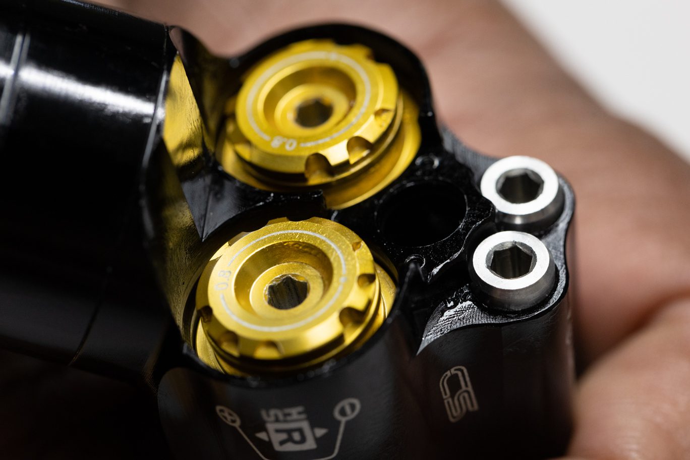
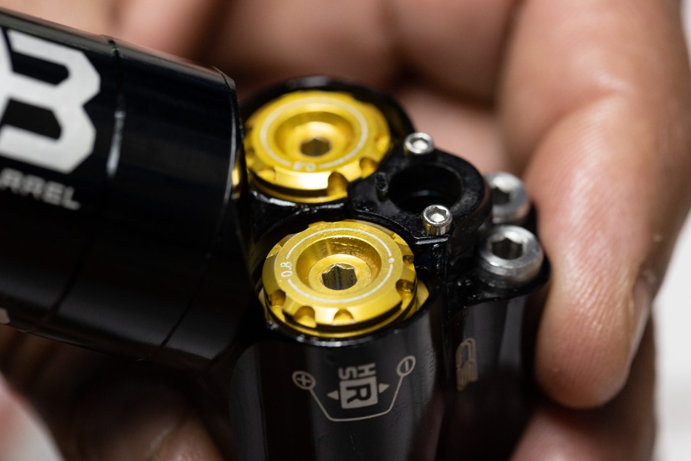
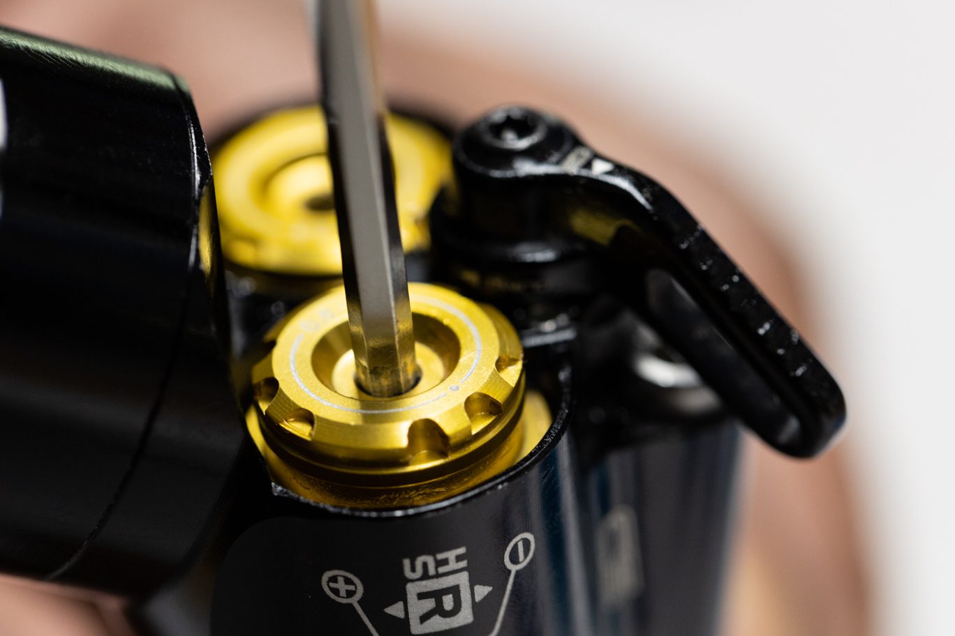
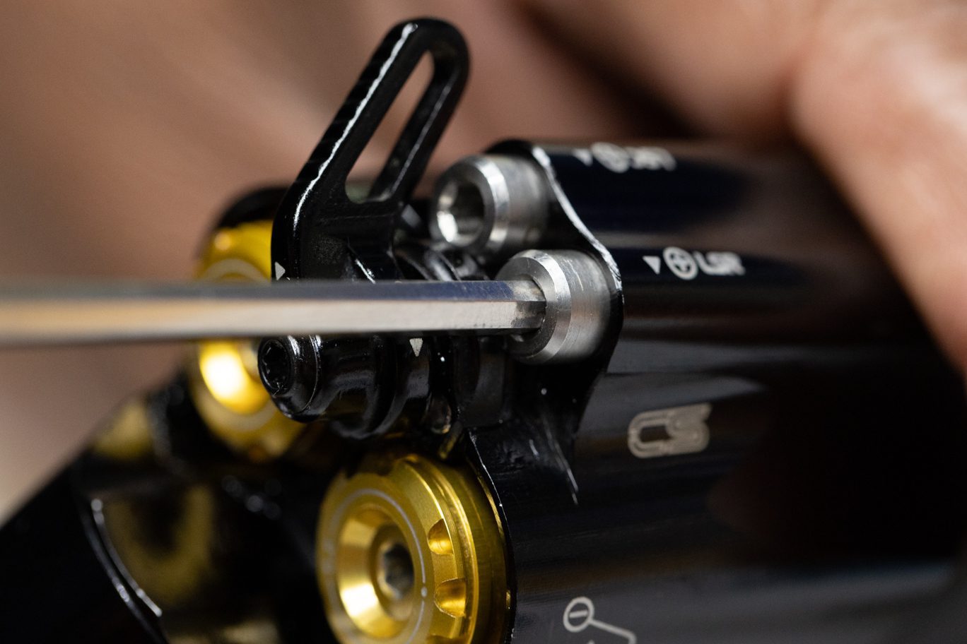
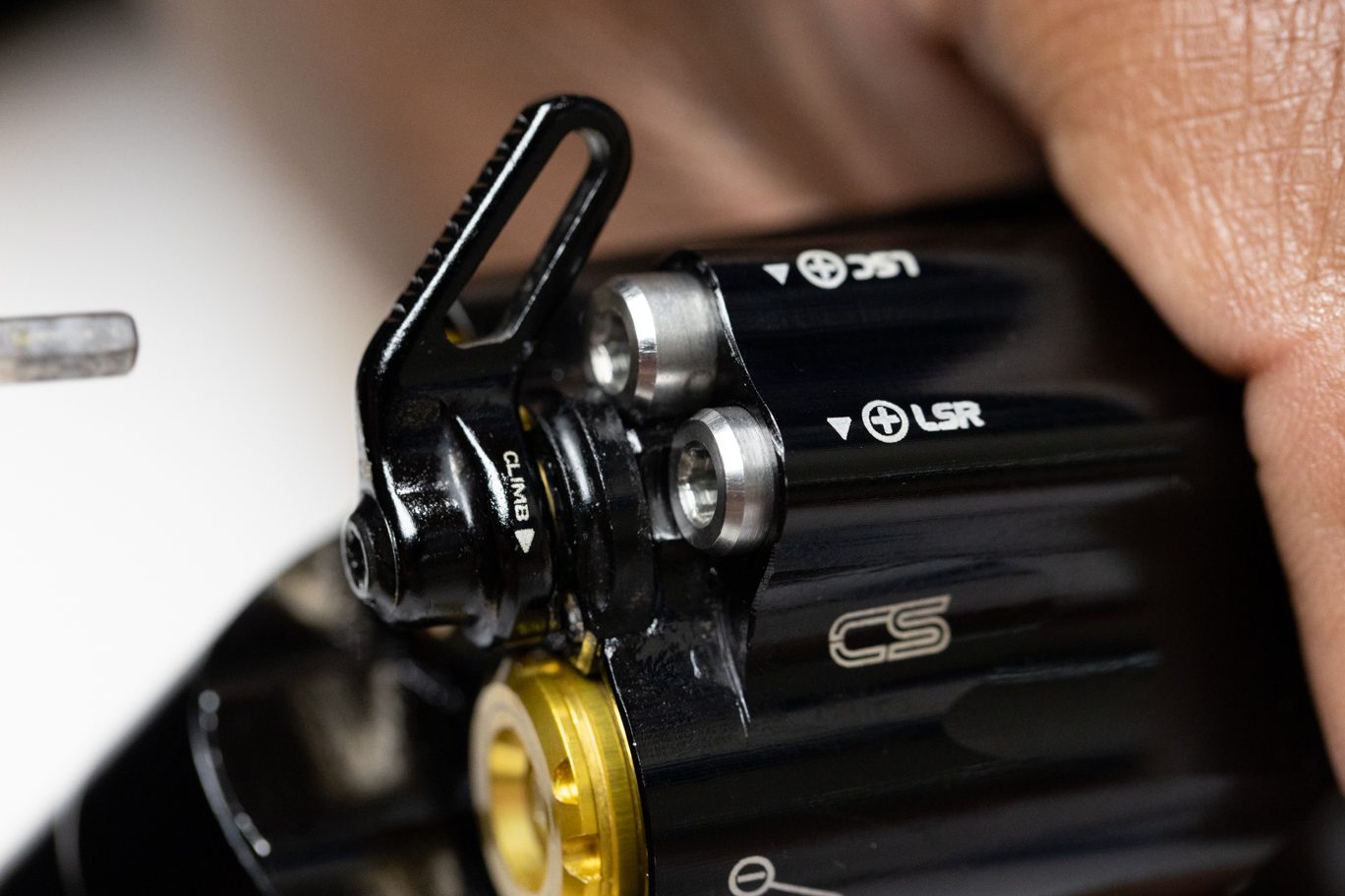
Step 2 – High Adjuster Install
Using 3mm Allen, install High Speed Rebound adjuster into Rebound housing. Thread below cover plate surface.
Using 3mm Allen, install High Speed Compression adjuster into Compression housing. Thread below cover plate surface.
High Speed Rebound Install 1
High Speed Rebound Install 2
High Speed Rebound Installed
High Speed Compression Install
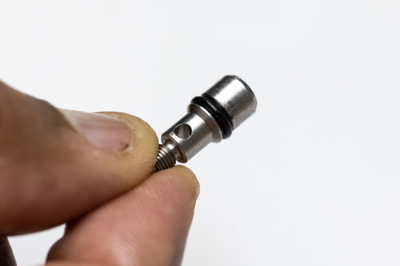
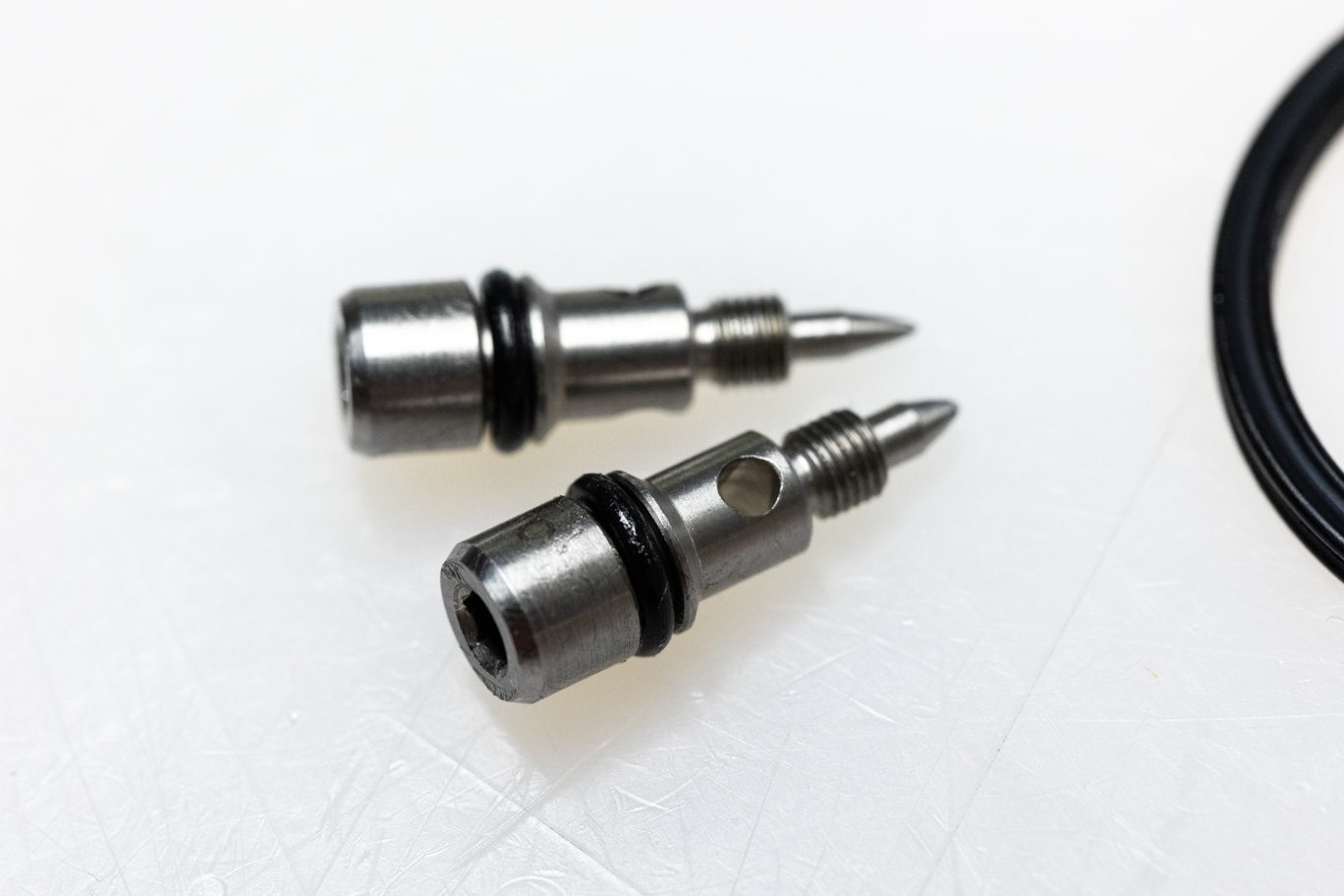
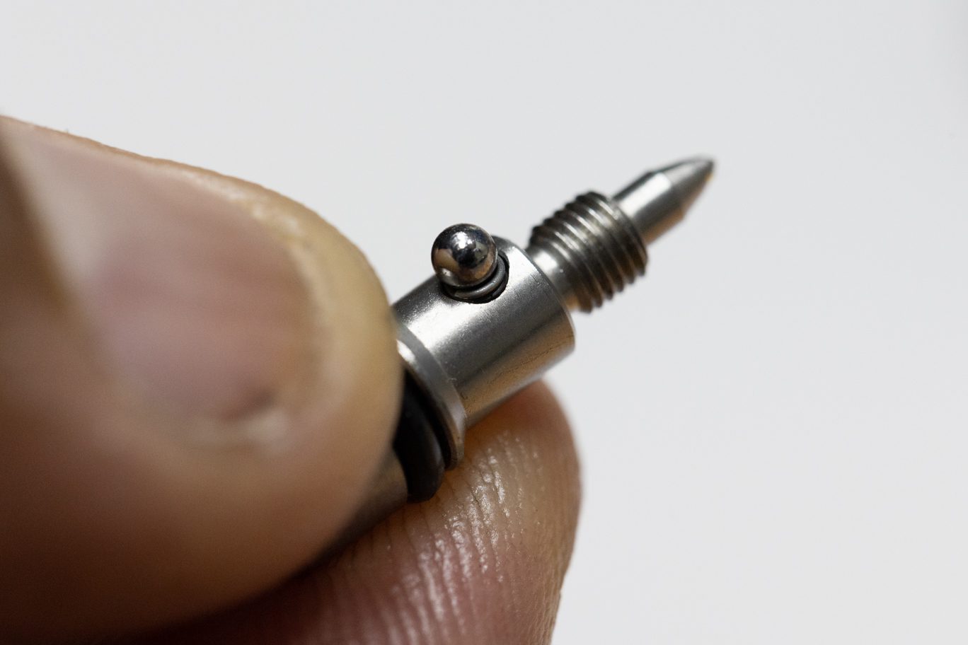
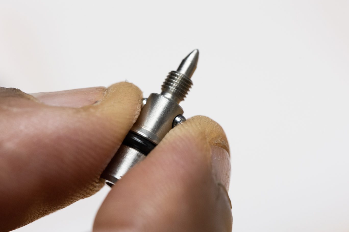
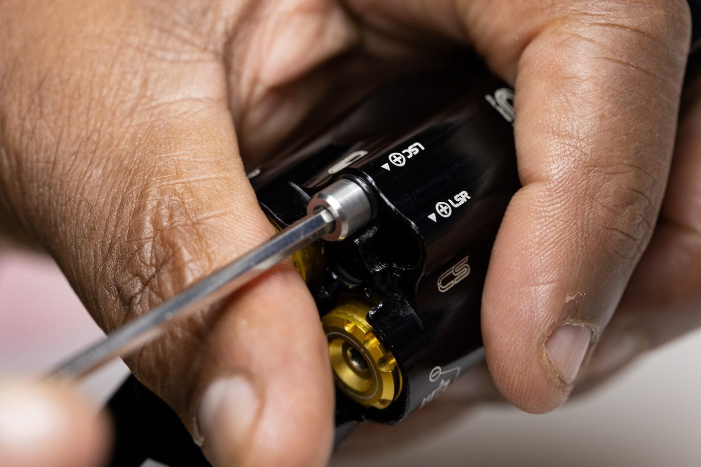
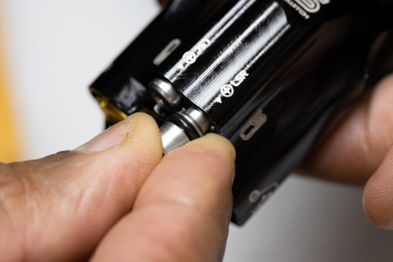
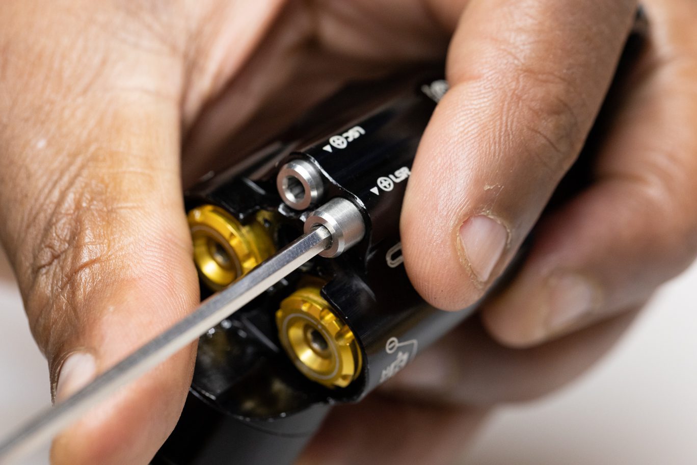
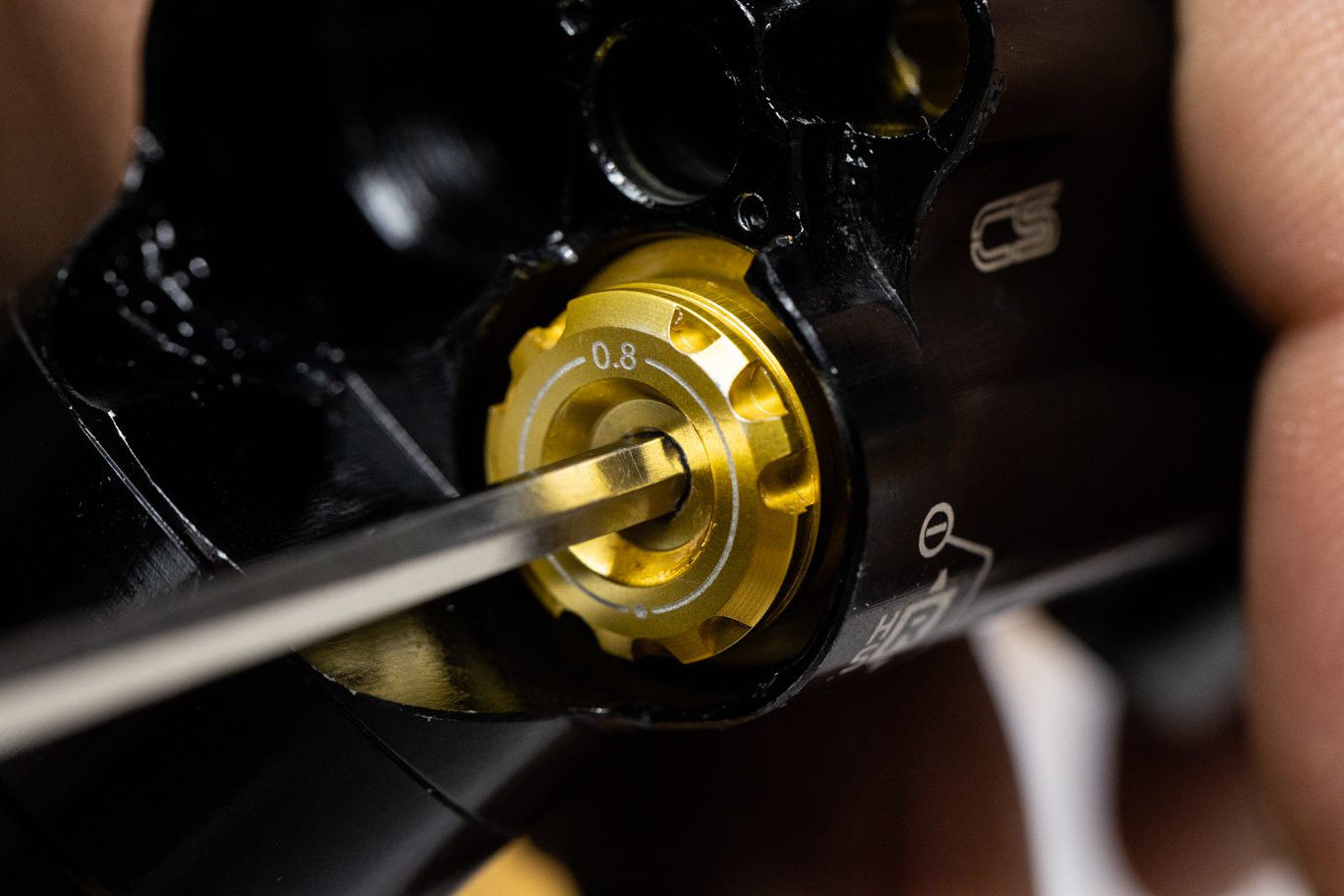
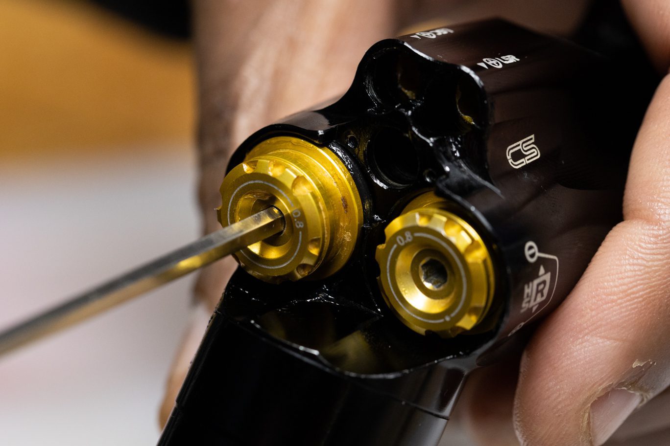
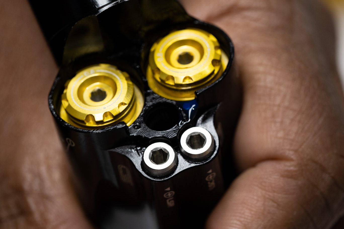
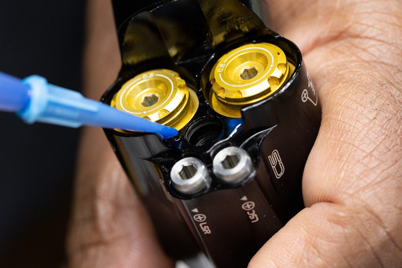
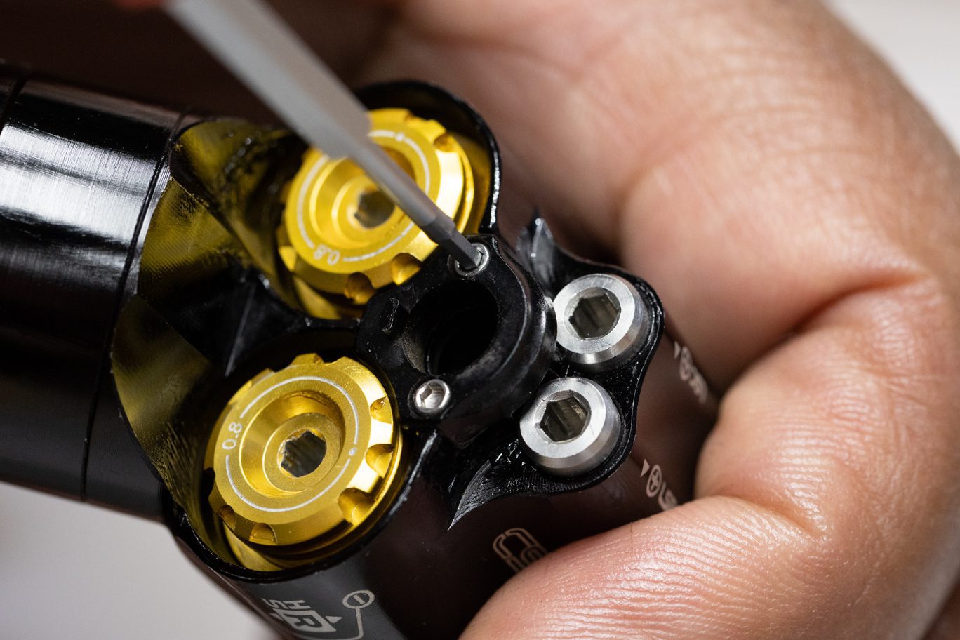
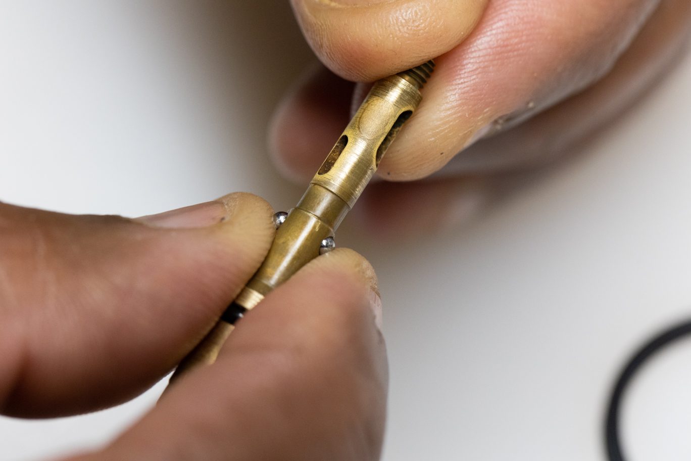
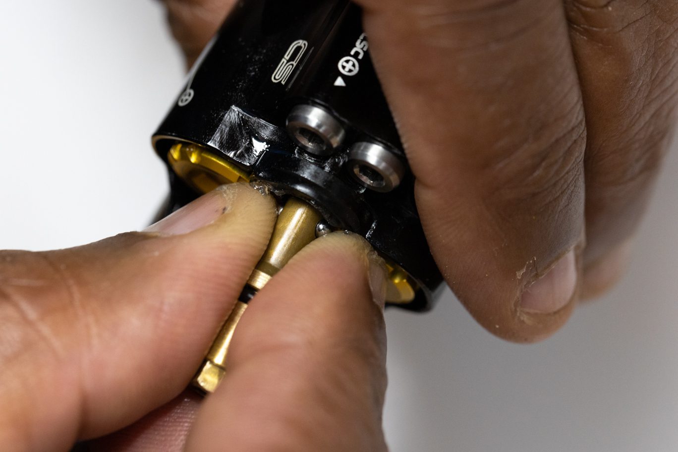
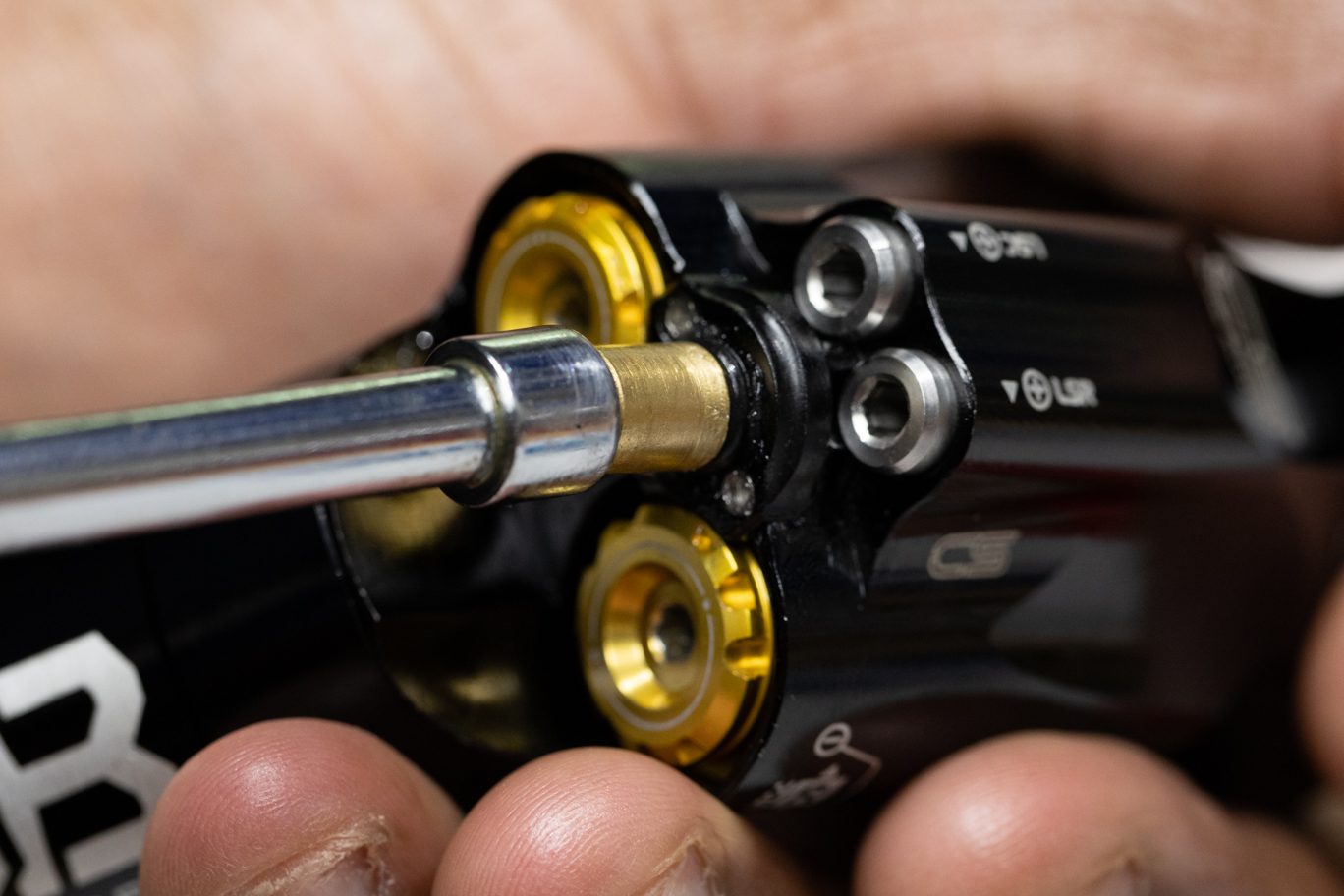
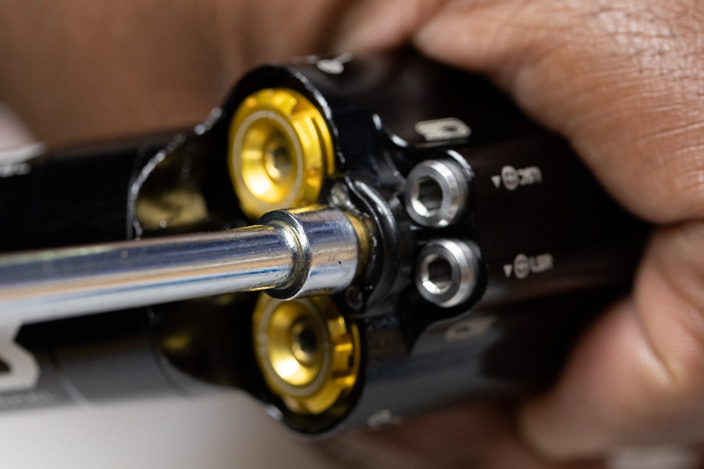
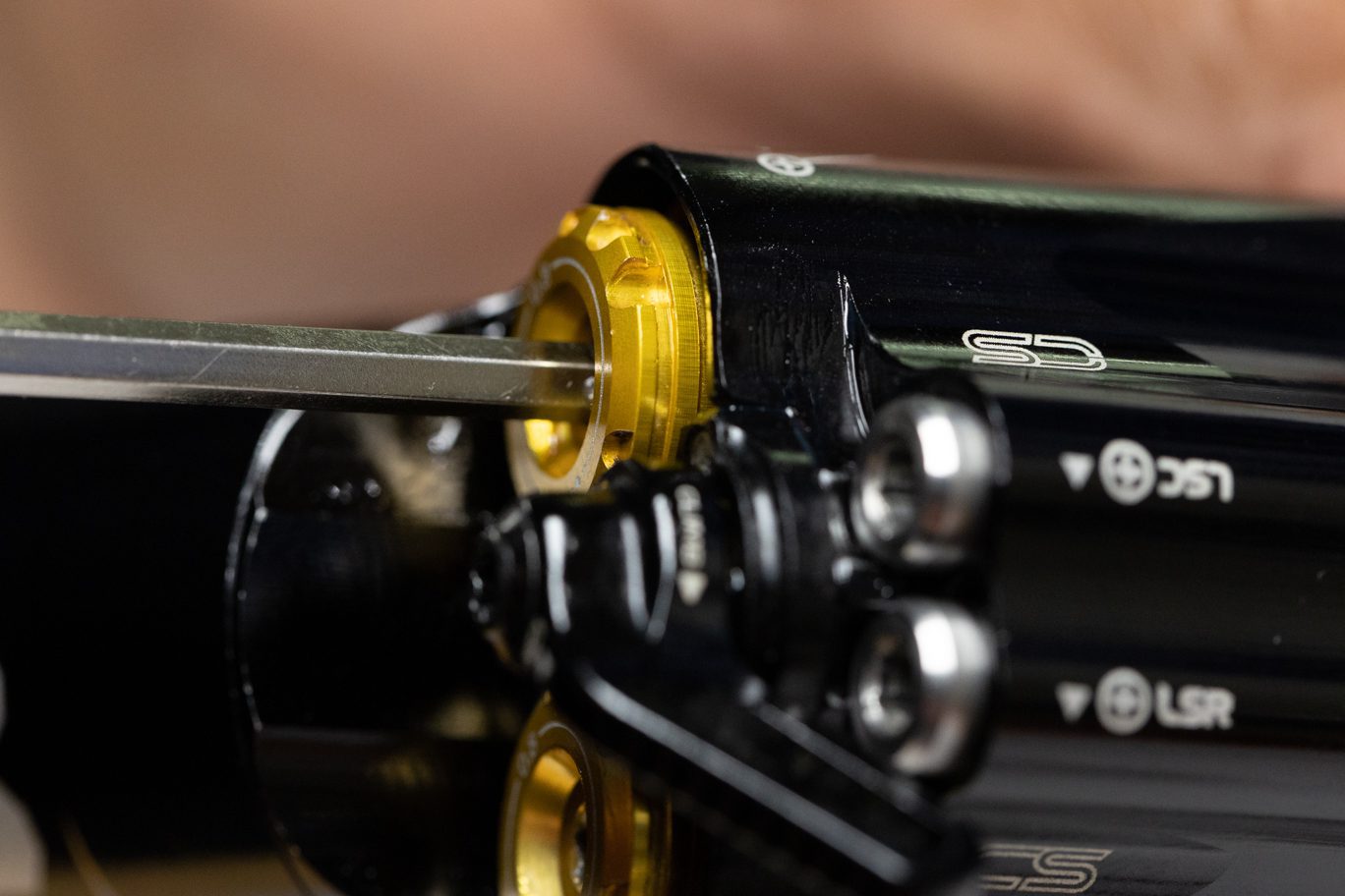
Step 3 – Low Speed Needle Install
Lightly grease and install low speed needle o-rings (.DB11102). Using grease, install detent ball, spring and second detent ball. Using 3mm Allen, install low speed needles into valve body. Be sure to match needle to original circuit. Thread needles below cover plate surface. Test for detent clicks at this time.
Low Speed Needle O-Ring Installed
Low Speed Needles O-Ring Installed
Low Speed Detent Balls & Spring Install
Low Speed Detent Balls & Spring Installed
Low Speed Compression Needle Install 1
Low Speed Compression Needle Install 2
Low Speed Rebound Needle Install 1
Low Speed Rebound Needle Install 1
Low Speed Needles Below Cover Plate Surface
Step 4 – Cover Plate Install
Apply blue (243) Loctite to cover plate screw holes on valve body. Install Climb Switch cover plate. Torque plate screws to 0.16 Nm with 1.5mm Allen. Be sure to tighten screws in an even pattern.
Applying Loctite to Cover Plate Screws 1
Applying Loctite to Cover Plate Screws 2
Cover Plate Install
Cover Plate Screws Install
Torquing Cover Plate Screws
Cover Plate Screws Installed
Step 5 – Climb Switch Spool Valve Install
Lightly grease and install spool valve o-ring (.DB11102). Lightly grease spool valve opening on cover plate. Using grease, install detent ball, spring and second detent ball. Install spool valve. Repeat removal process of threading spool valve all the way closed (clockwise) then opening (counterclockwise) 1/2 turn and onto indicator dot at 6:00.
Spool Valve O-Ring Installed
Greasing Cover Plate Interior
Spool Valve Detent Balls & Spring Installed
Spool Valve Install
Threading Spool Valve
Clocking Spool Valve
Spool Valve Installed & Clocked
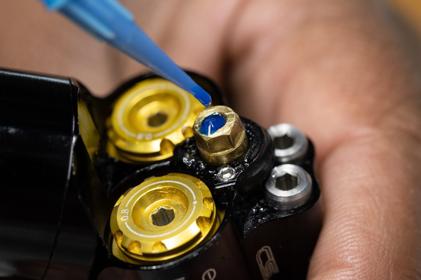


Step 6 – Climb Switch Lever Install
Apply blue (243) Loctite to internal threads on spool valve. Install Climb Switch with lever pointing towards the Rebound adjusters (in the climb switch “on” position). Install Climb Switch screw and torque to 1.2 Nm using a T10 wrench. Back out both low and high speed adjusters until gently touching the cover plate.
Spool Valve O-Ring Installed
CS Lever Clocked & Installed
CS Lever Screw Install
CS Lever Screw Installed
Backing Out HSR to Cover Plate
Backing Out HSC to Cover Plate
Backing Out LS Needles to Cover Plate
LSC Needle Backed Out to Cover Plate
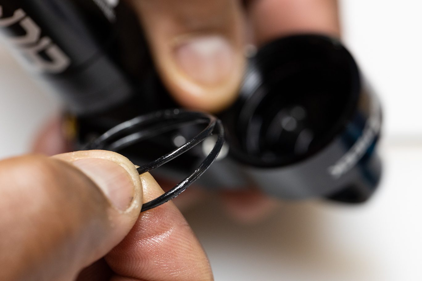
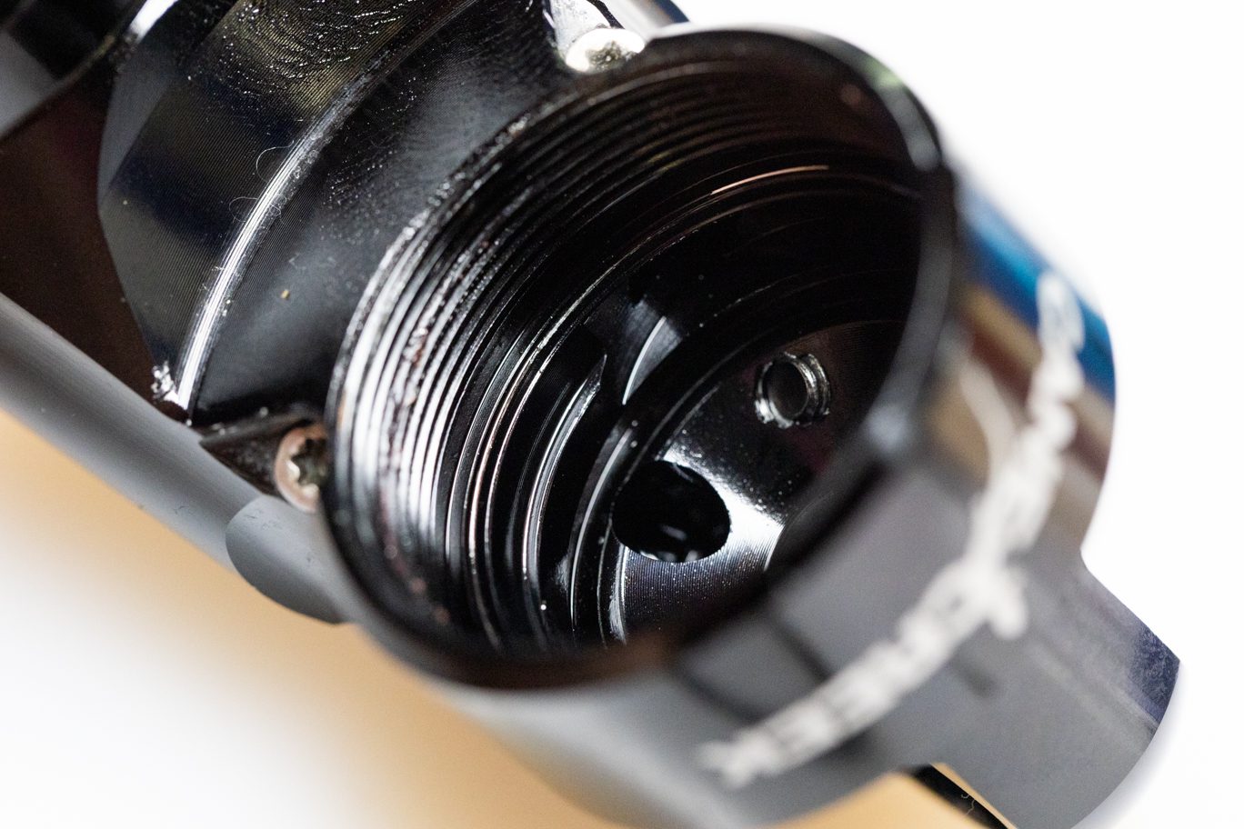
Step 7 – Outer Damper Install (if necessary)
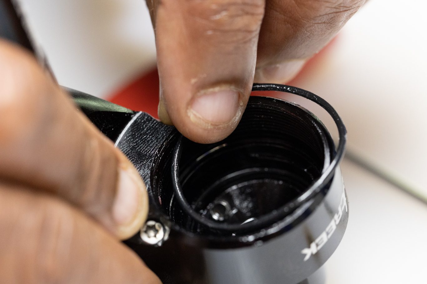
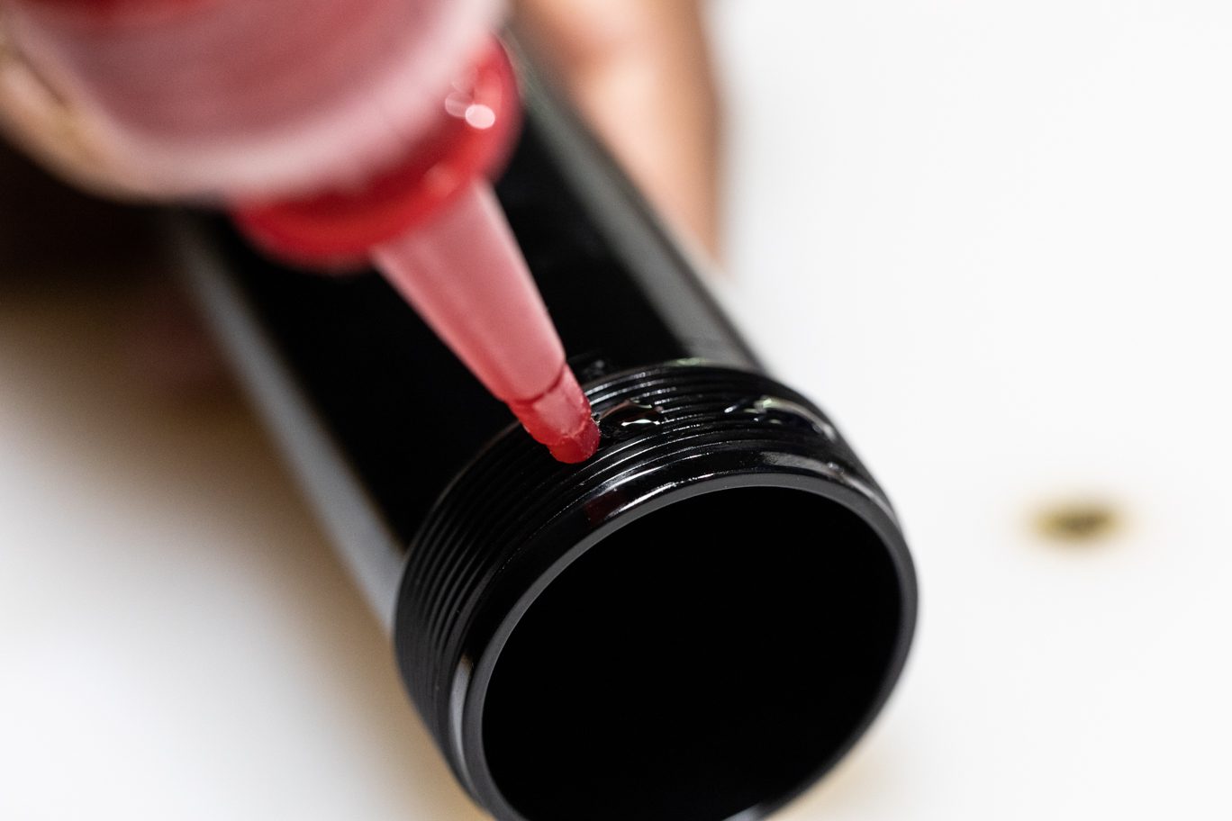
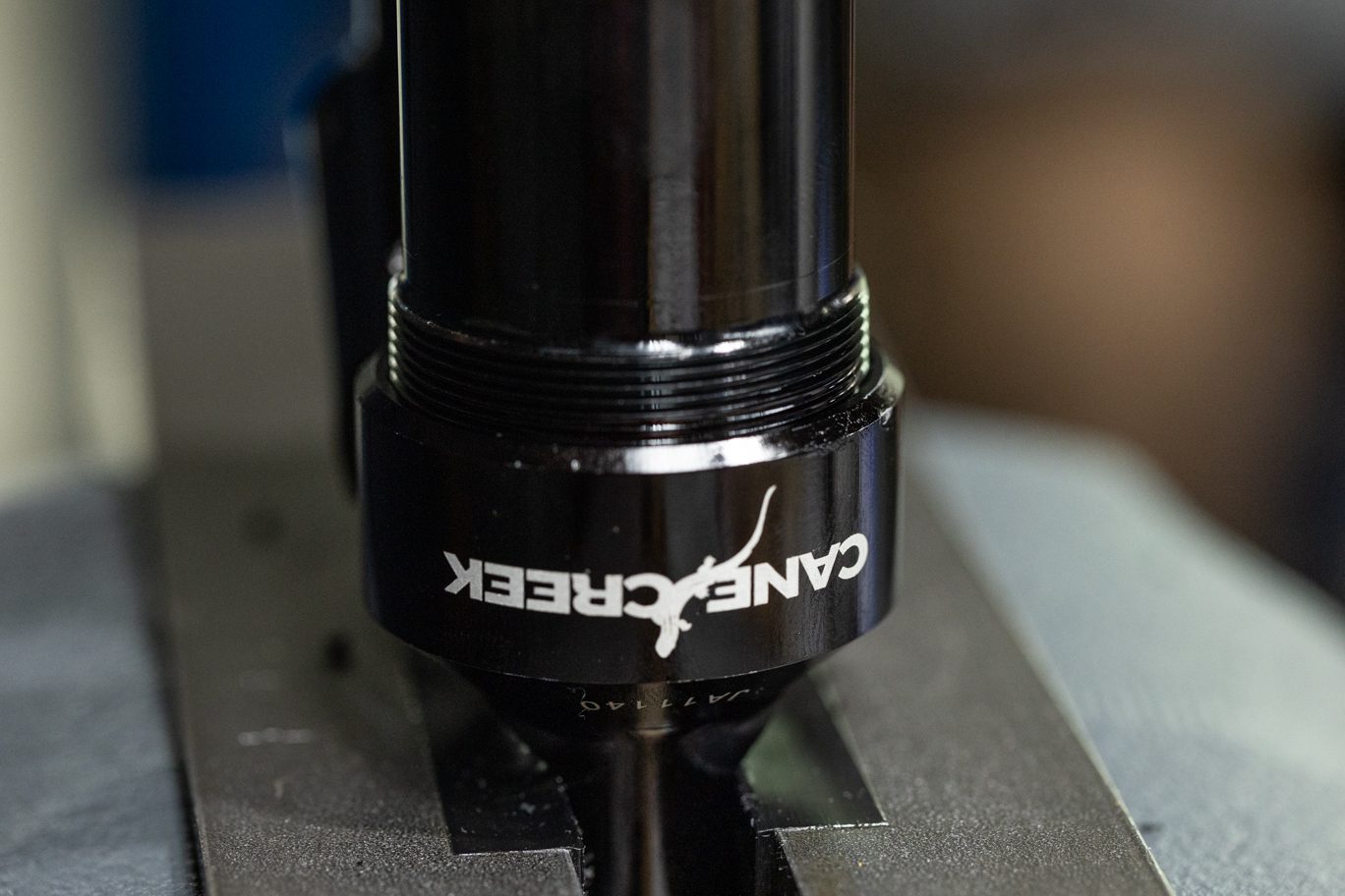
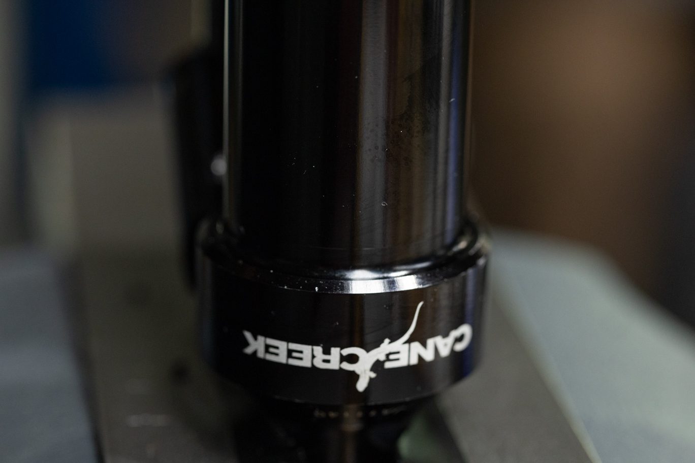
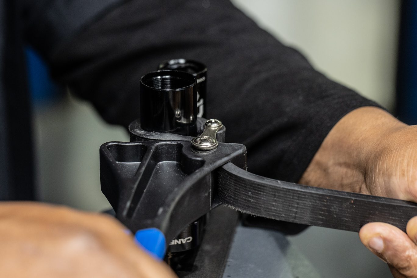
Lightly grease and install damper tube o-rings (.DB11110 & .DB11109) in cylinder head. Apply small amount of red (263) Loctite to outer damper tube threads. Thread outer damper tube into cylinder head. Tighten in place with strap wrench.
Greased Damper Tube O-Rings
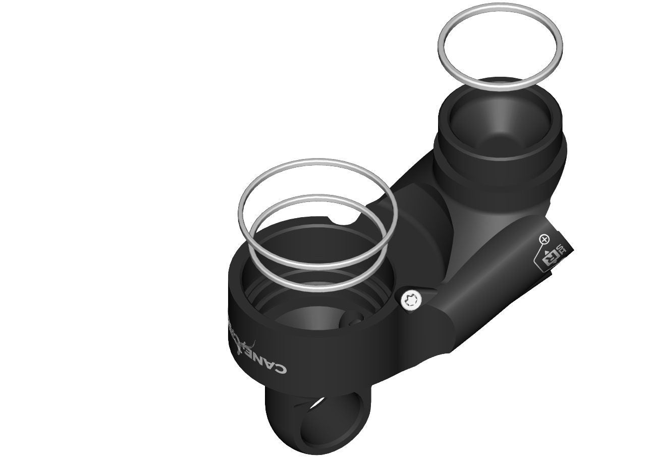
Damper Tube O-Ring Channels
Damper Tube O-Ring Install
Valve Body O-Rings for Outer Damper Tube & Res Tube
Damper Tube O-Rings Installed
Applying Loctite to Outer Damper Tube
Loctite Applied to Outer Damper Tube
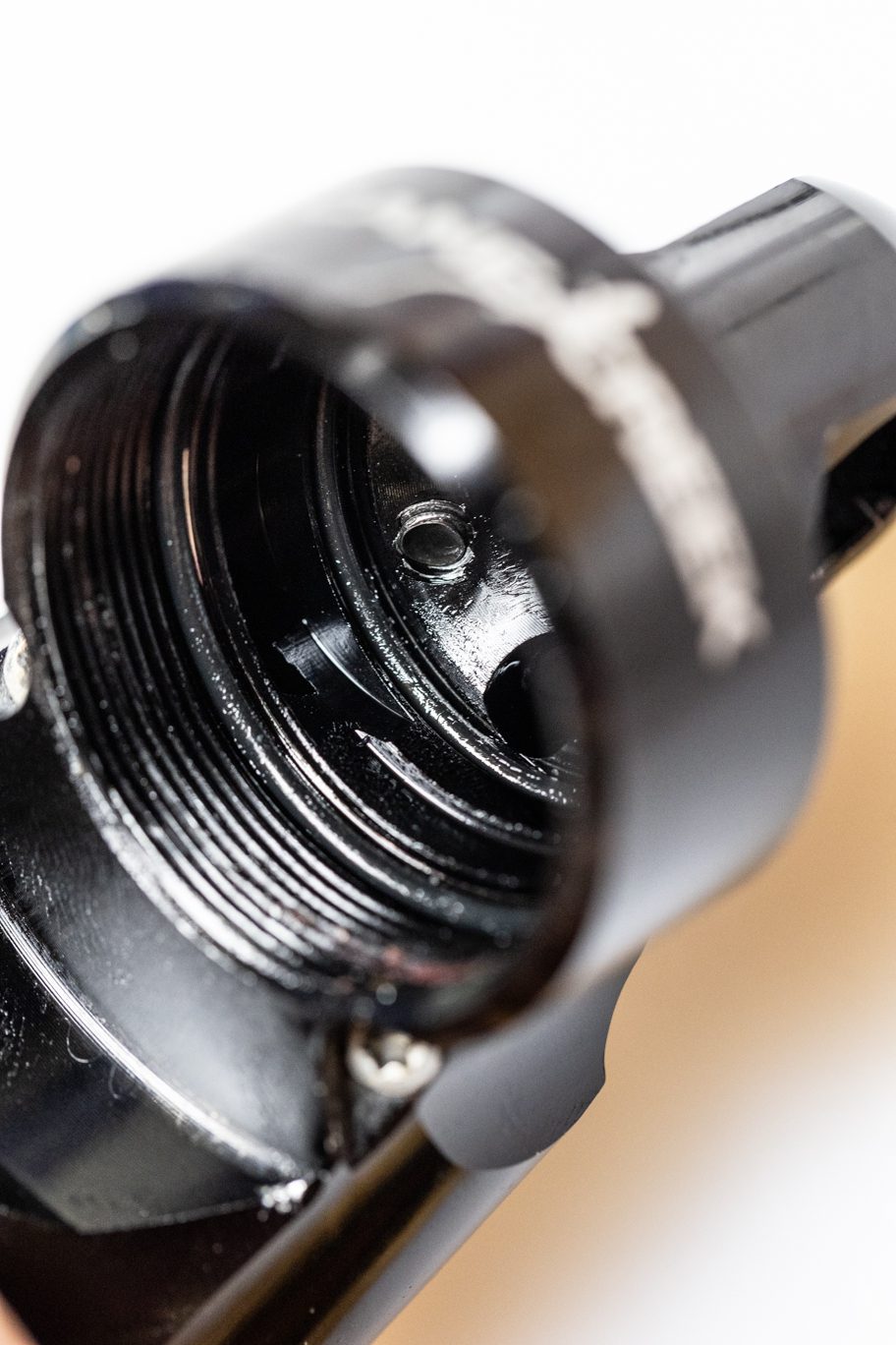
Threading Outer Damper Tube into Cylinder Head
Outer Damper Tube Threaded into Cylinder Head
Tightening Outer Damper Tube
Step 8 – IFP Install
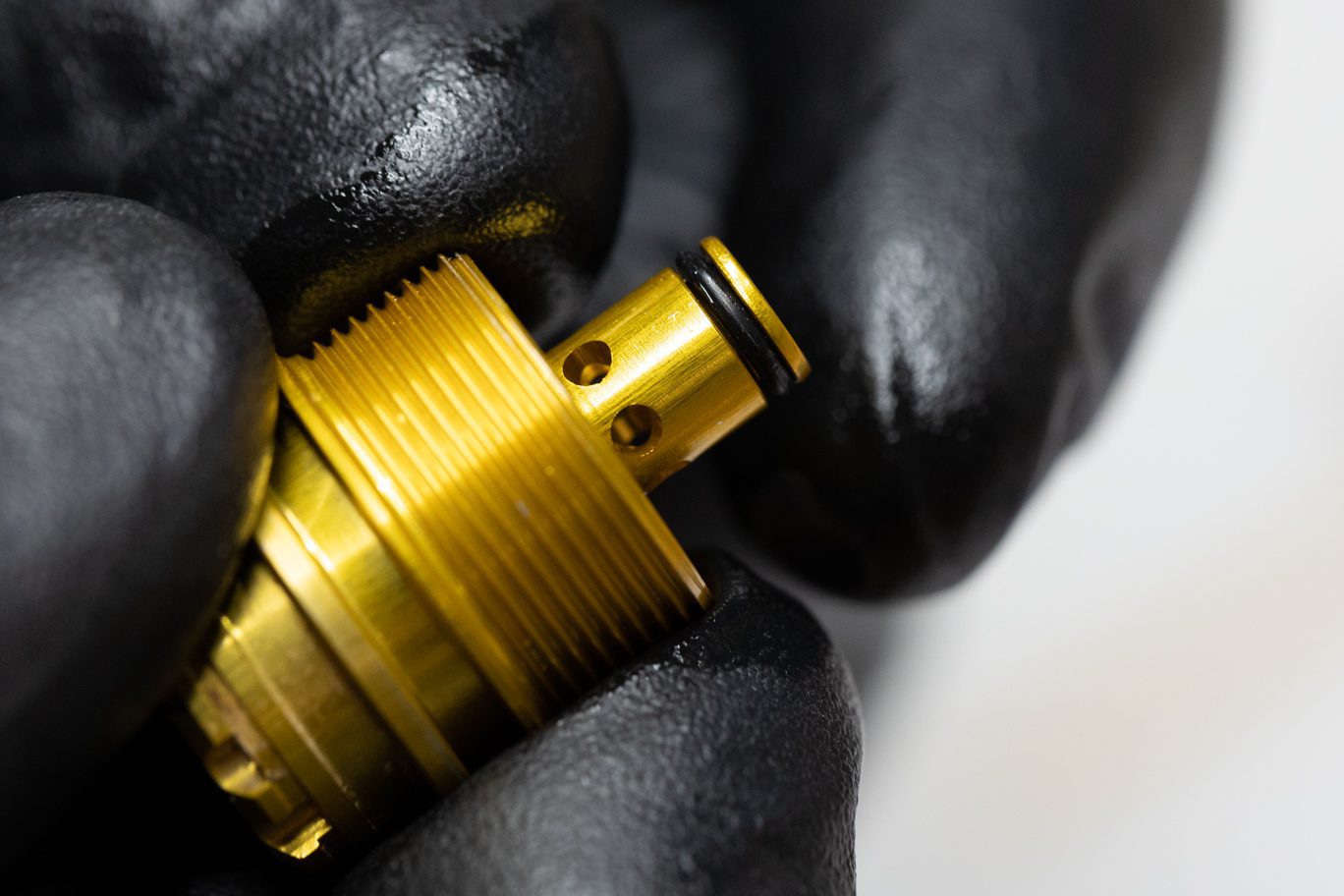
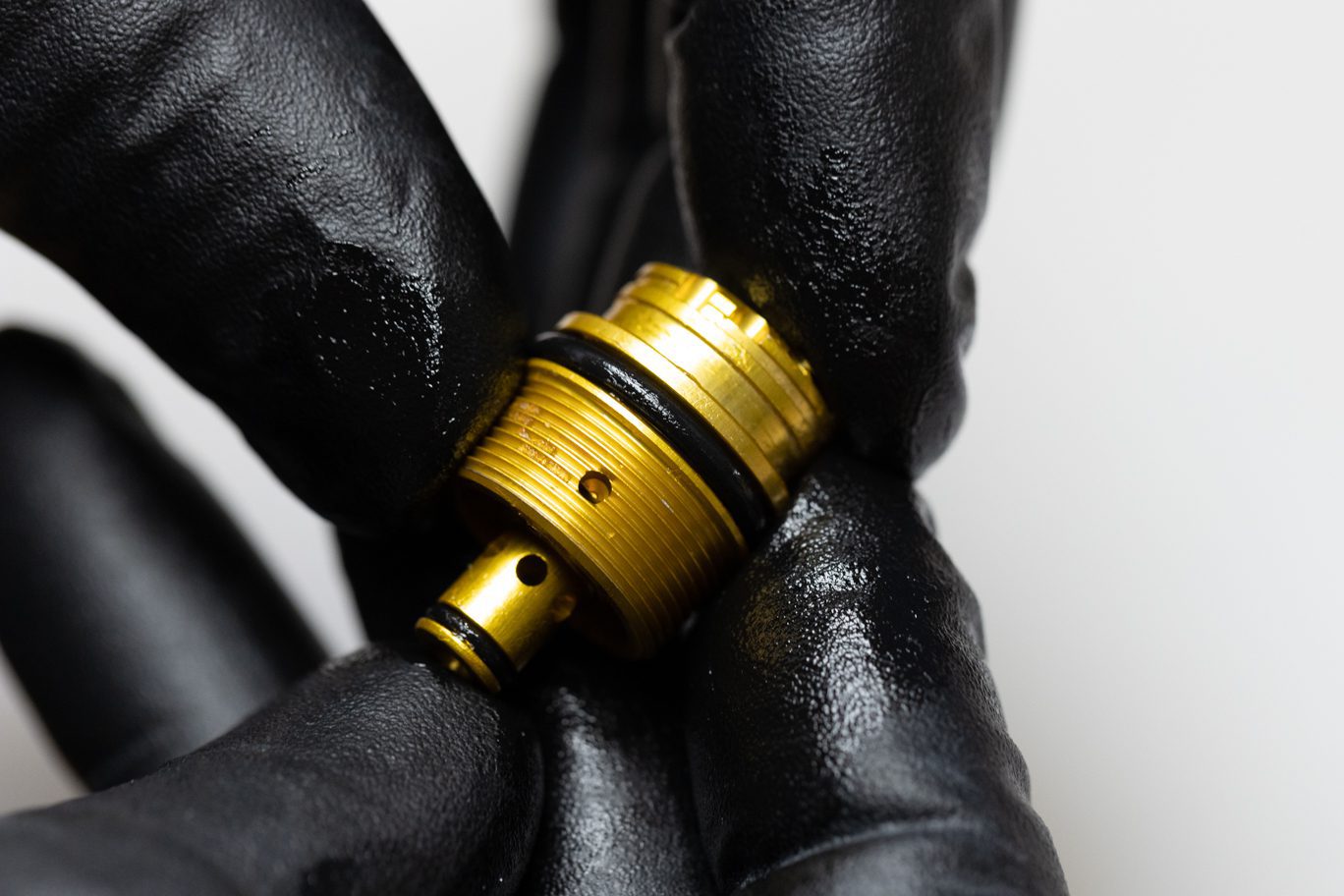
Lightly grease and install IPF quad ring (.DB11120). Lightly grease wall of reservoir tube and install IFP by pushing tube onto piston.
IFP & Quad Ring
Greasing IFP Quad Ring
IFP Quad Ring Install
Greasing Reservoir Tube Wall
IFP Install 1
IFP Install 2
IFP Installed


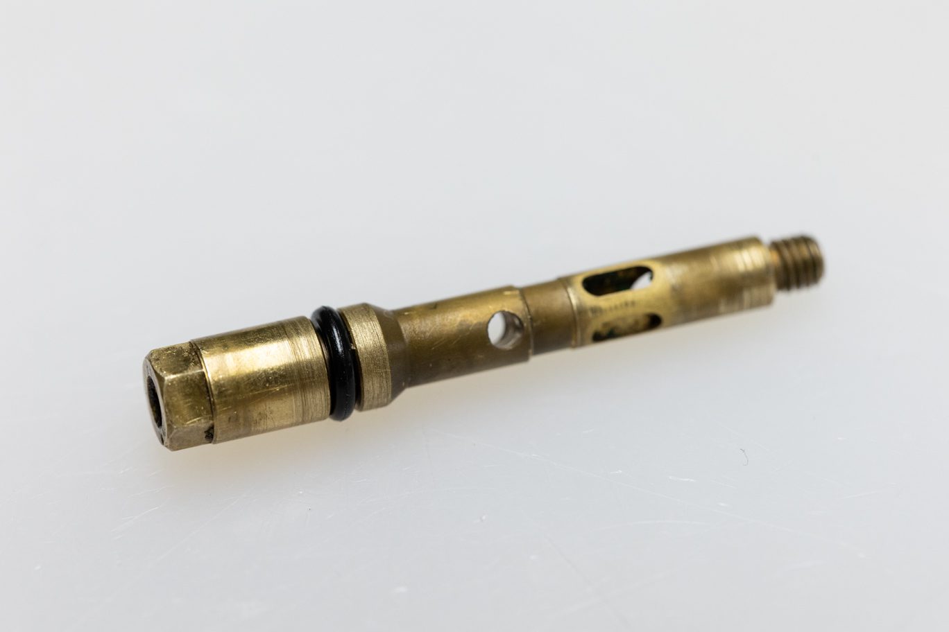
Step 9 – Inner Damper Tube & Oil Seal Head Install
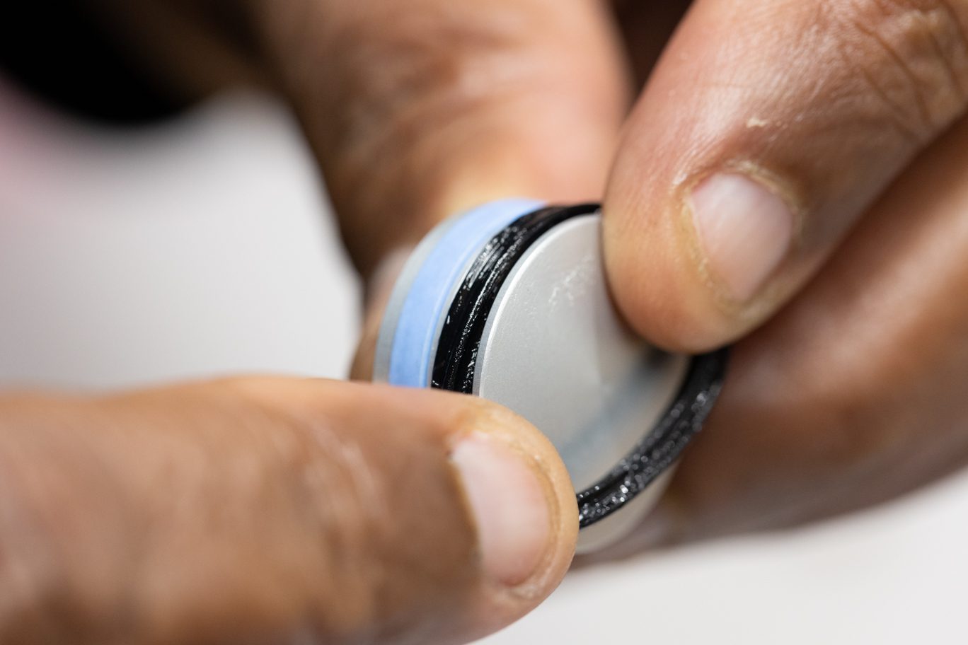
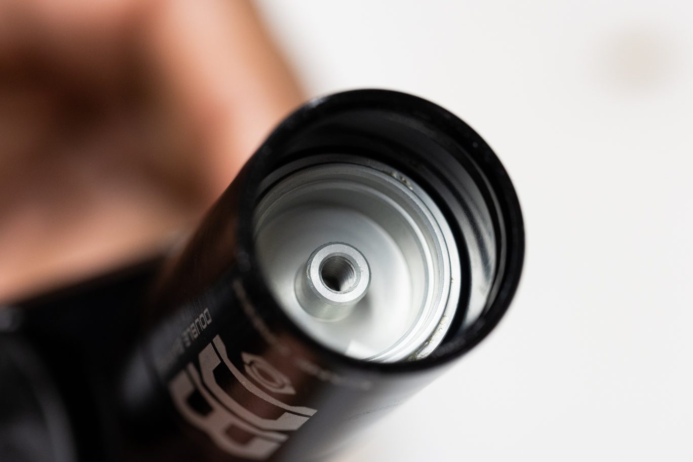
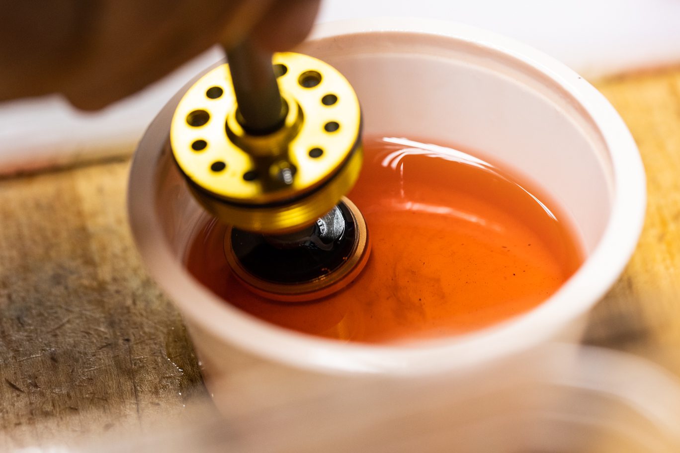
Coat piston with shock oil and insert shaft assembly into inner damper tube. Note location of holes on seal head end. Install inner damper tube/shaft assembly into outer damper tube. Thread oil seal head into outer damper tube and torque to 15 Nm using Oil Seal Head wrench.
Coating (Air) Piston
Inserting Piston into Inner Damper Tube
Proper Orientation of Seal Head & Inner Damper Tube
Inserting Shaft Assembly/Inner Damper Tube into Outer Damper Tube
Oil Seal Head Torqued to Outer Damper Tube
Continue to Part 3
Next