
HELM Coil Spring Side Complete 100 Hour Service
HELM Coil Spring Complete 100 Hour Service Instructions
June 2022 orig.
Recommendations and Warnings
Cane Creek recommends only trained suspension technicians perform service on all suspension, using all required tools and following all proper procedures. Anyone without access to the proper equipment or with any concerns on the procedures should defer to an authorized Cane Creek service center for service. Improper service can result in loss of performance or suspension failure. All Cane Creek forks have pressurized oil. Follow the service procedures exactly as written to avoid possible injury or harm to the suspension. Always wear eye protection while performing suspension service. Please dispose of all waste products and materials through proper channels to avoid contamination of the environment.
Any damage or issues resulting from improper service will not be covered by warranty. If you have a fork still in its original warranty period and do not wish to void your warranty, please contact an authorized Cane Creek service center.
These service instructions cover the basic service procedures using standard service kits. If your suspension requires parts beyond standard replacement parts – CSU, compression rods, etc. – please consult your authorized Cane Creek service center or contact us at our Cane Creek Support Center.
Service Notes
These instructions cover just the coil spring leg of a complete 100 hour service. Combine these instructions with the appropriate damper side and 50 hour lower service to get a complete 100 hour fork service.
Additionally, you can send the damper for a service with an authorized Cane Creek service center.
Service Kit
none
Required Cane Creek Tools
none
Additional Tools & Supplies
Torx wrenches – T10
Sockets – 15mm & chamfer-less 30mm
Crowfoot wrenches – 22mm
Open Ended Box wrenches – 22mm
8mm shaft clamp (if needed)
Torque wrenches
Pick
Suspension Grease
PolyLube Grease
Torque, Loctite, Oil & Nitrogen Specs
Torque & Loctite Chart
| Part | Torque Spec | Loctite Spec |
|---|---|---|
| Comp Rod Stop | 6 Nm | 263 (Red) |
| Seal Head Install | 16 Nm | None |
| Preloader | 36 Nm | 243 (Blue) |
| Preloader Cap Screw | 1.6 Nm | 243 (Blue) |
Related Technical Service Bulletins
Review all related TSBs before performing any service.
TSB027 – Compression Rod Top Out Changes
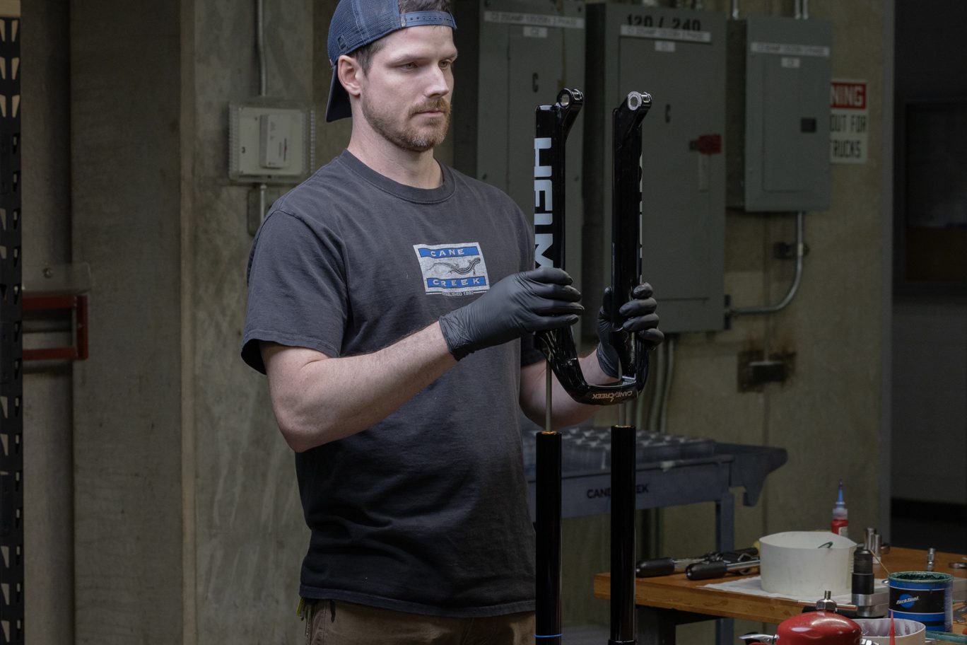
Lower Assembly Removal
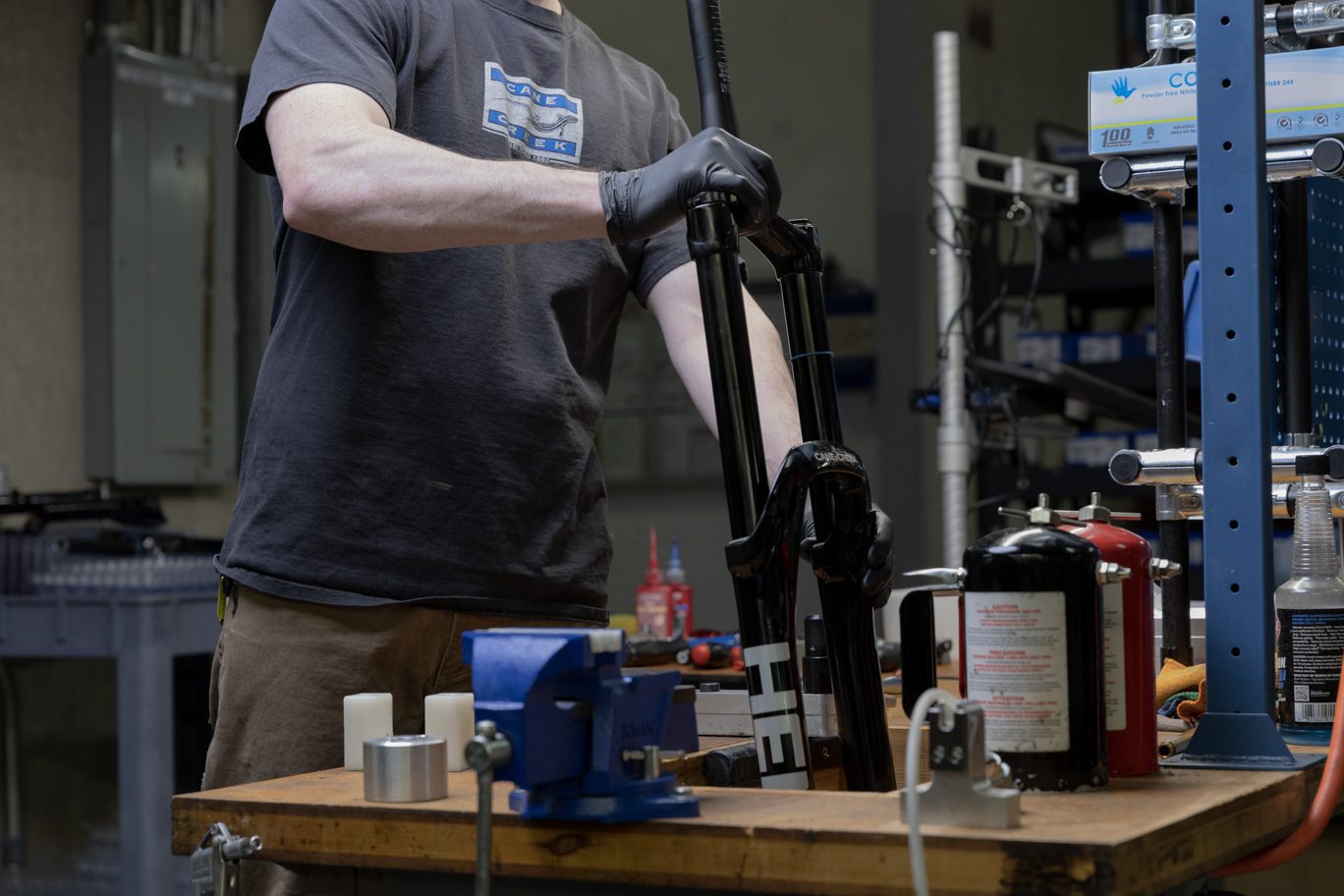

Prior to beginning spring service, remove the lower assembly per the 50 hour service instructions.
Removing CSU from Lowers 1
Removing CSU from Lowers 2
Spring Assembly Removal
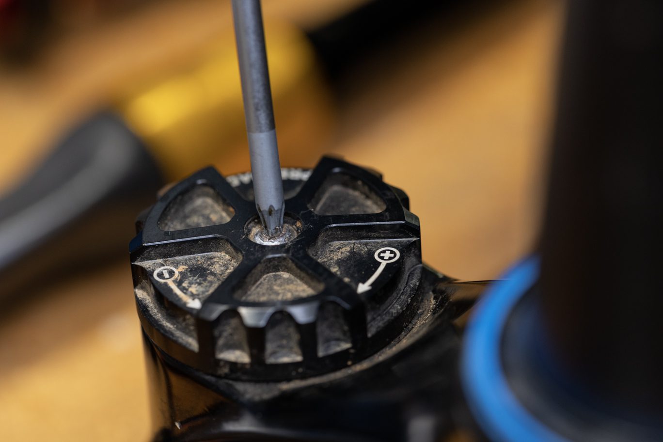
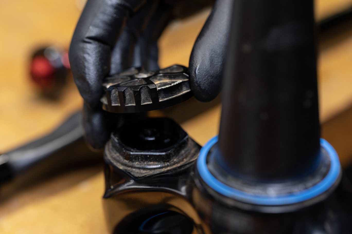
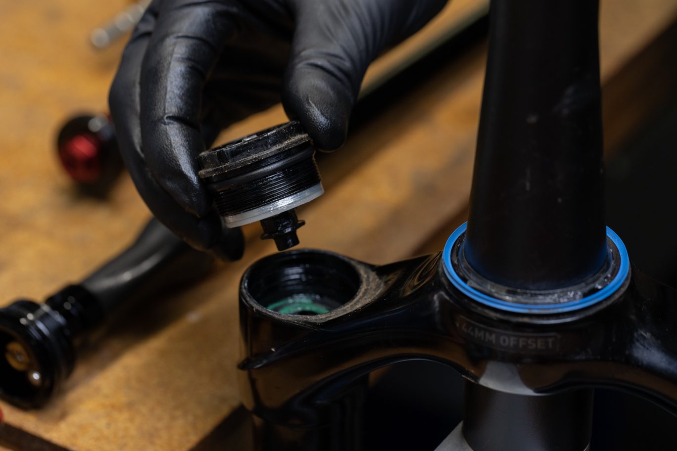
Step 1 – Preloader Assembly Removal
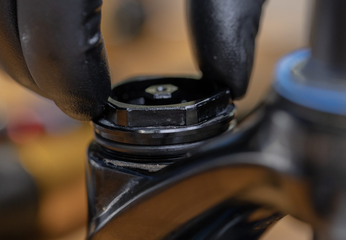
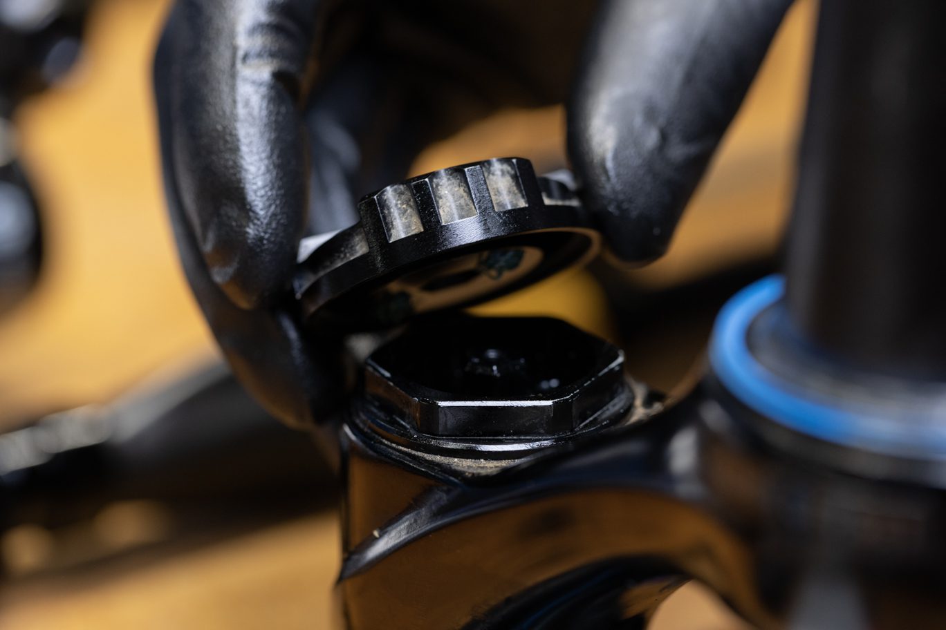
Secure CSU. Using T10 Torx, remove spring preloader cap. Using 30mm chamferless socket, remove preloader assembly. Breaker bar may be necessary.
Preloader Top Cap Screw Removal
Preloader Top Cap Removal
Freeing Preloader Assembly
Preloader Assembly Removed
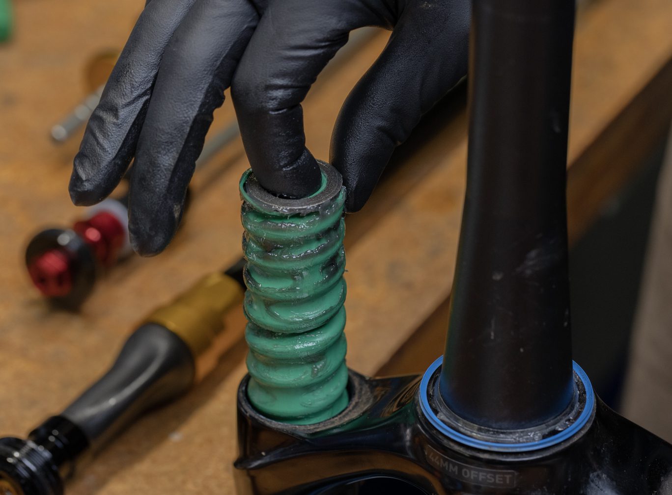
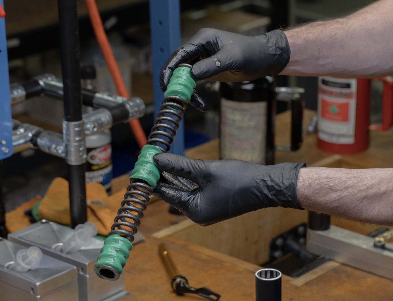
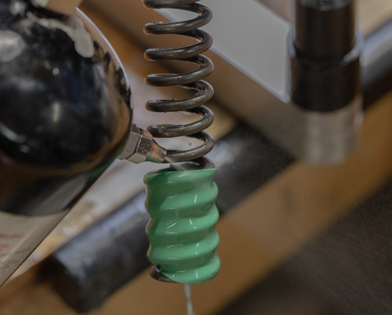
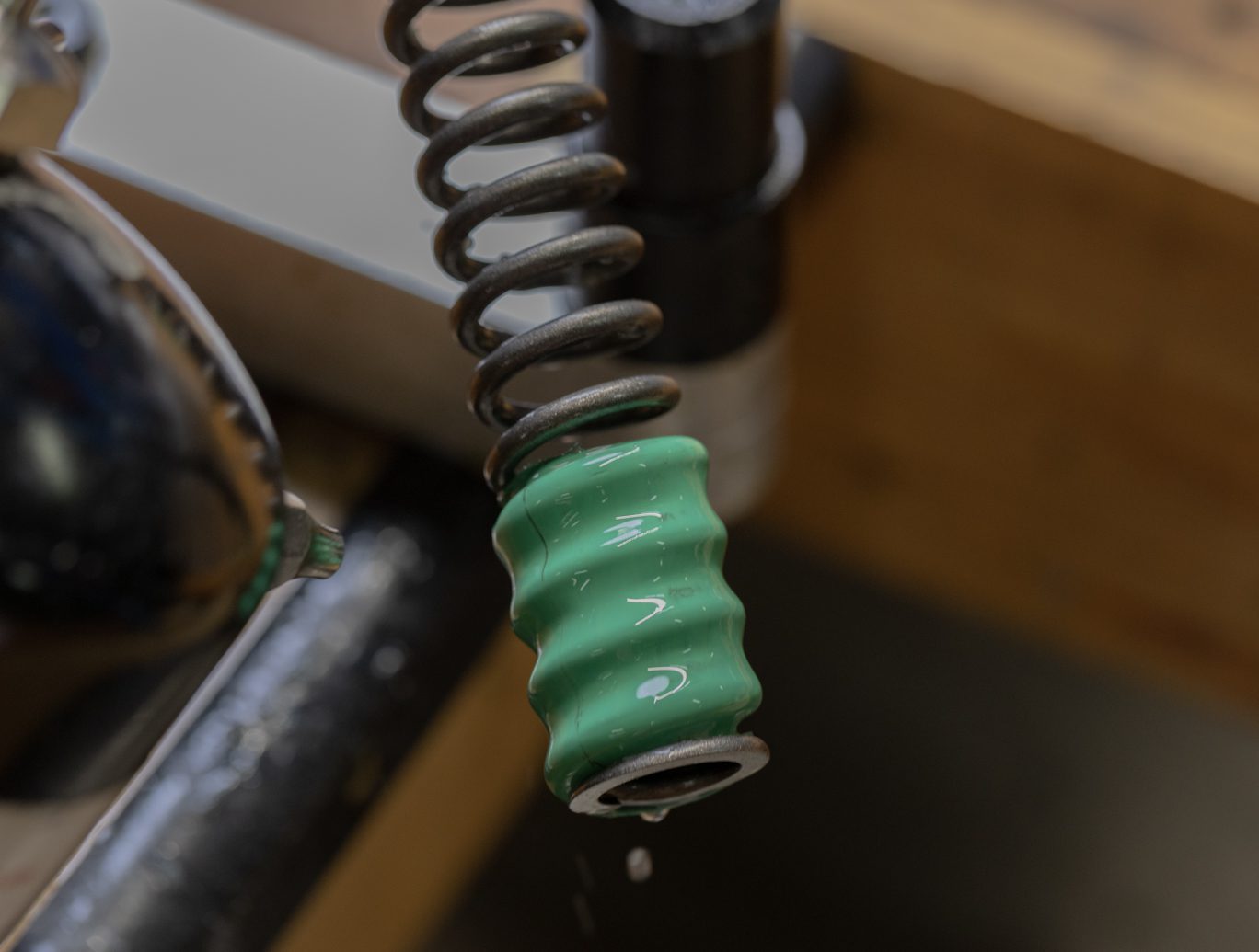
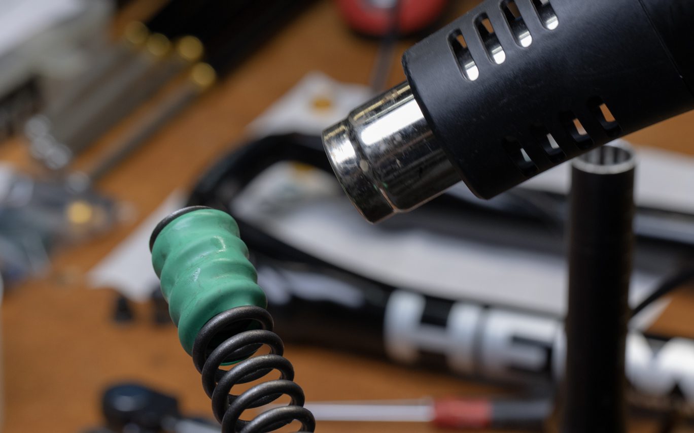
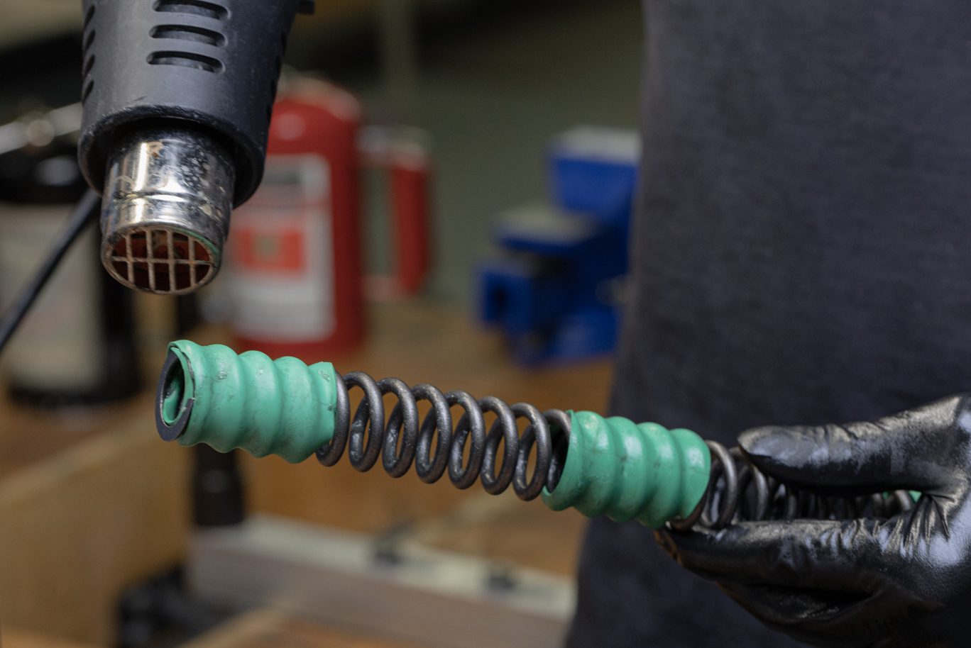
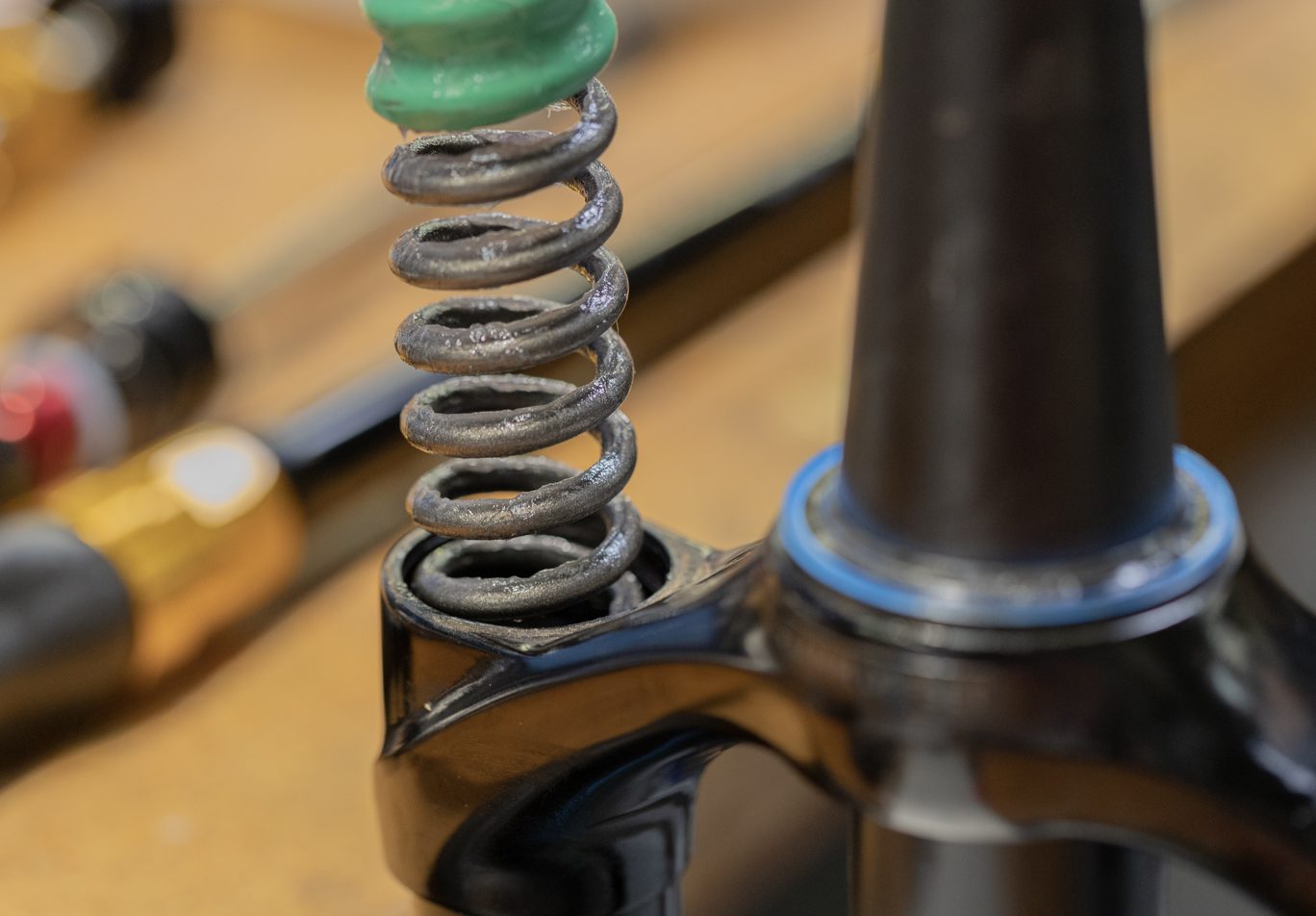
Step 2 – Spring Removal
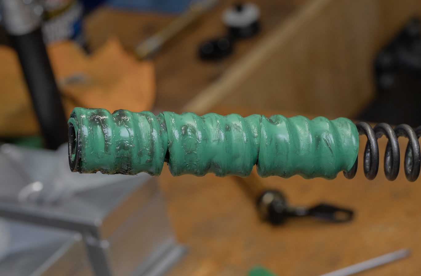
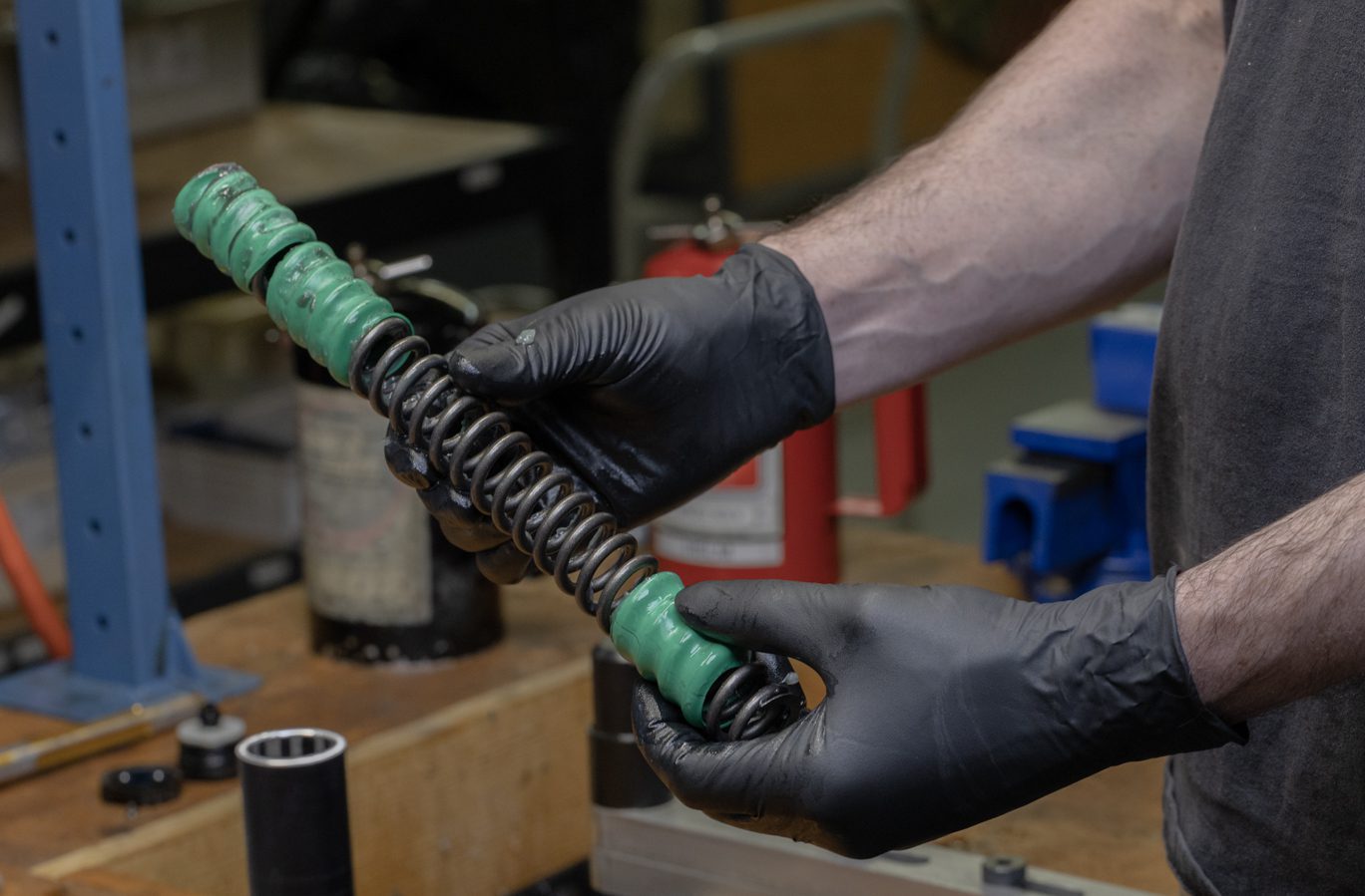
Remove spring and inspect sleeve location. Clean spring thoroughly. Reposition sleeves for even spacing. Apply heat to sleeves to affix them in place.
Spring Removal
Spring Sleeves in Wrong Location 1
Spring Sleeves in Wrong Location 2
Spring Sleeves Properly Positioned
Cleaning Spring 1
Cleaning Spring 2
Heating Sleeves 1
Heating Sleeves 2


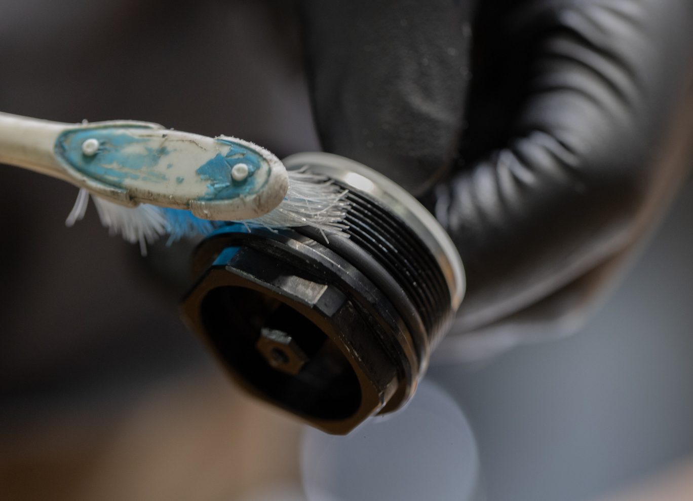
Step 3 – Compression Rod Assembly Removal
Using a 22mm open ended wrench, unthread coil seal head from stanchion. Remove coil compression rod assembly. Remove and discard footnut o-ring. Clean all oil from compression rod assembly using diluted alcohol. Inspect top out bumpers. Note that top out bumpers and configuration from factory may vary from photos here.
Freeing Comp Rod Assembly
Comp Rod Assembly Removal
Comp Rod Assembly Removed
Footnut O-Ring Removal
Cleaning Comp Rod Assembly


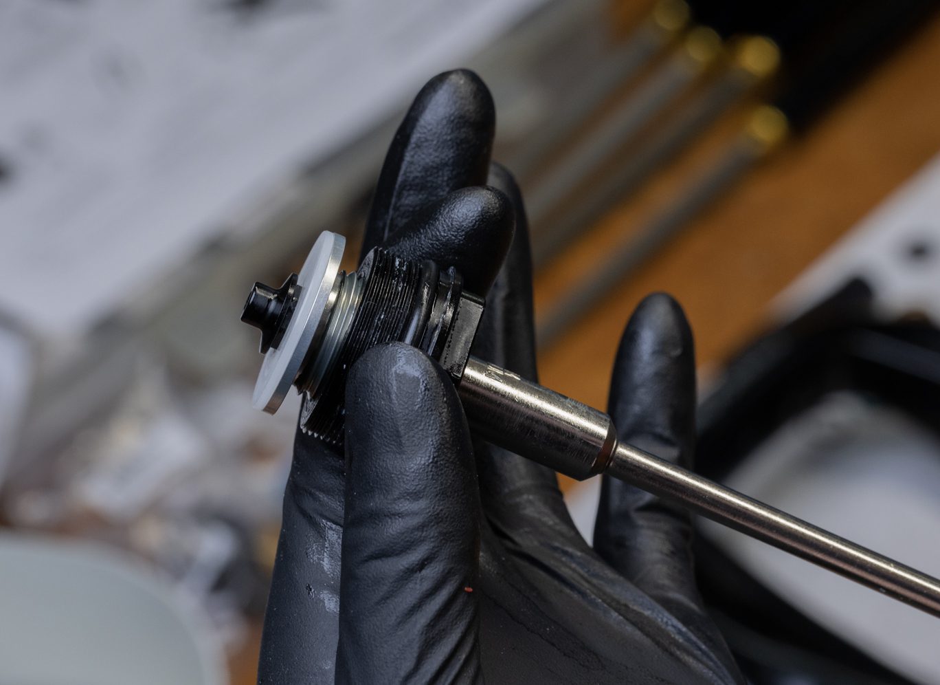
Step 4 – Compression Rod Disassembly (if needed)
If needed to replace or add top out bumpers only.
Using 8mm shaft clamp, secure shaft between spring perch and top out bumpers. Using 15mm socket, remove compression rod stop. Remove spring perch, collet, and top out bumpers as necessary.
TSB027 – Compression Rod Top Out Changes
Comp Rod Clamped for Rod Stop Removal
Rod Stop Removal
Rod Stop Removed
Collet Removal
Collet Removed
Spring Perch Removal
Top Out Bumpers Removal
Top Out Bumpers Removed
Spring Assembly Install


Step 1 – Compression Rod Assembly (if needed)
Install top out bumpers, collet, and spring perch. Ensure holes are lined up on the collet and perch. Apply red (263) Loctite to threads on shaft. Install compression rod stop. Clamp shaft and torque compression rod stop to 6 Nm using 15mm socket.
Top Out Bumpers Install
Top Out Bumpers Installed
Spring Perch Install
Collet Install
Collet Installed
Proper Alignment of Perch & Collet
Applying Loctite to Threads
Rod Stop Install 1
Rod Stop Install 2
Rod Stop Torque


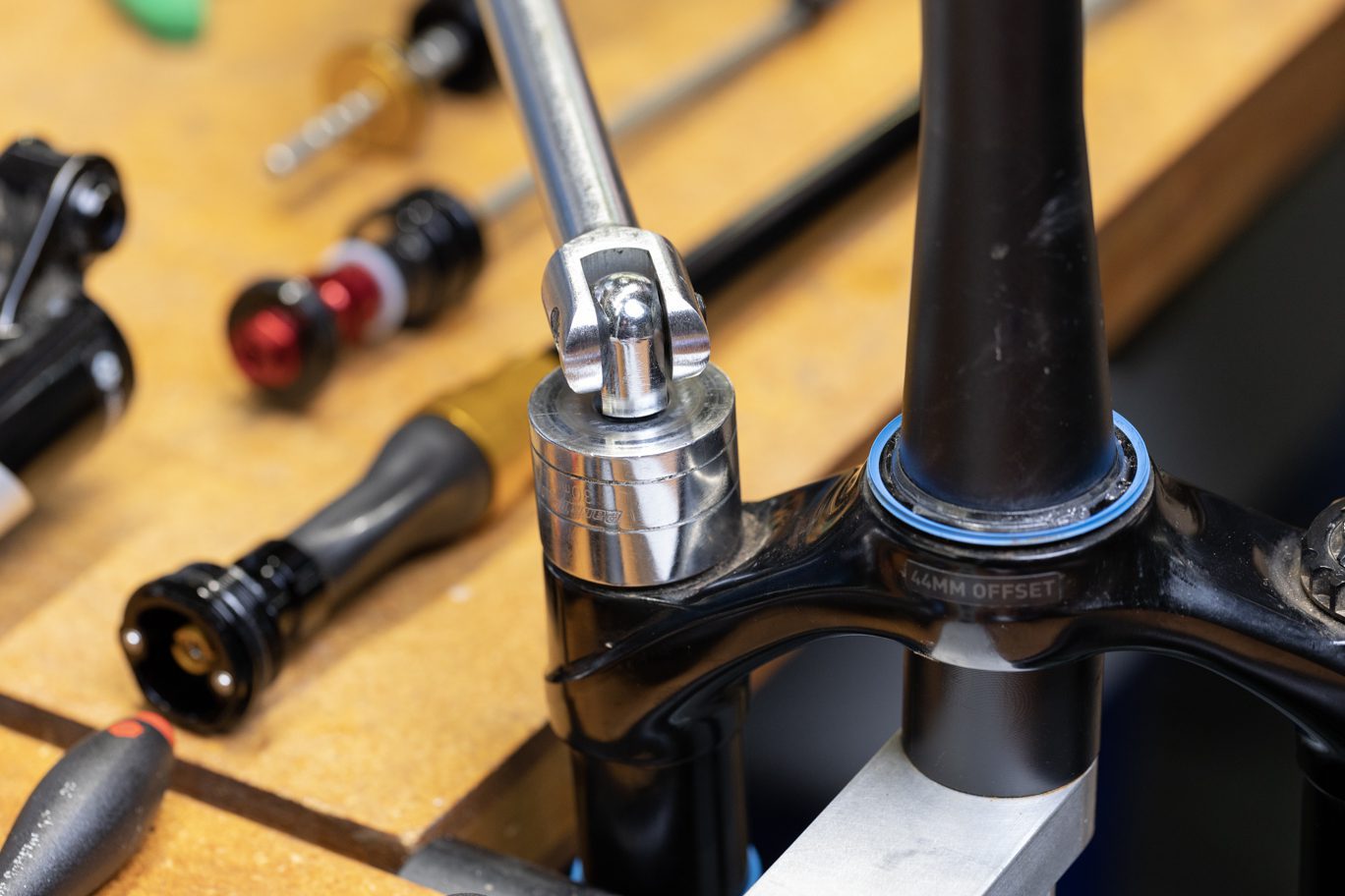
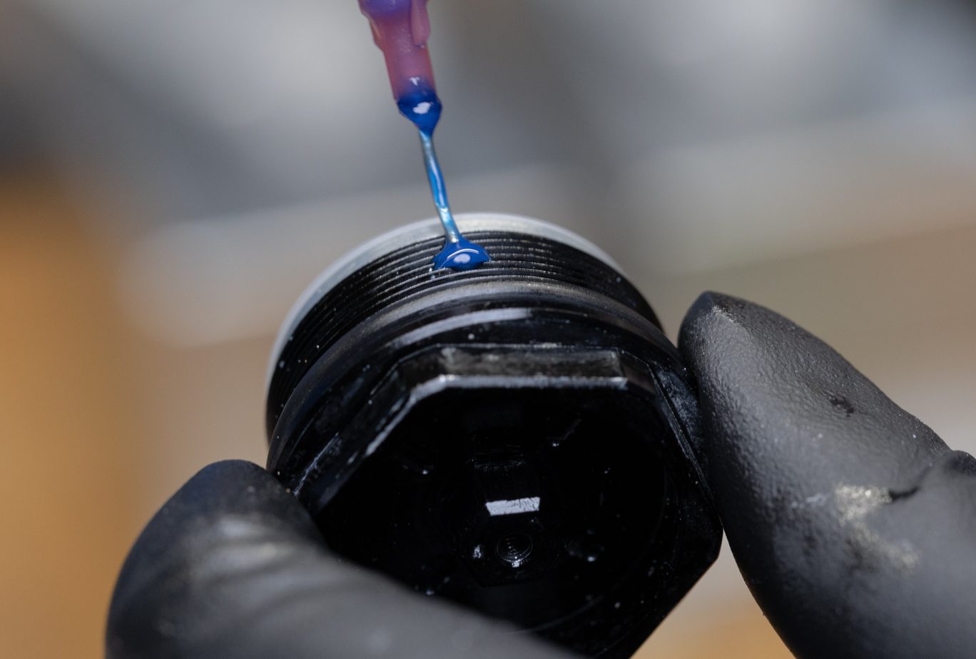
Step 2 – Compression Rod Assembly Install
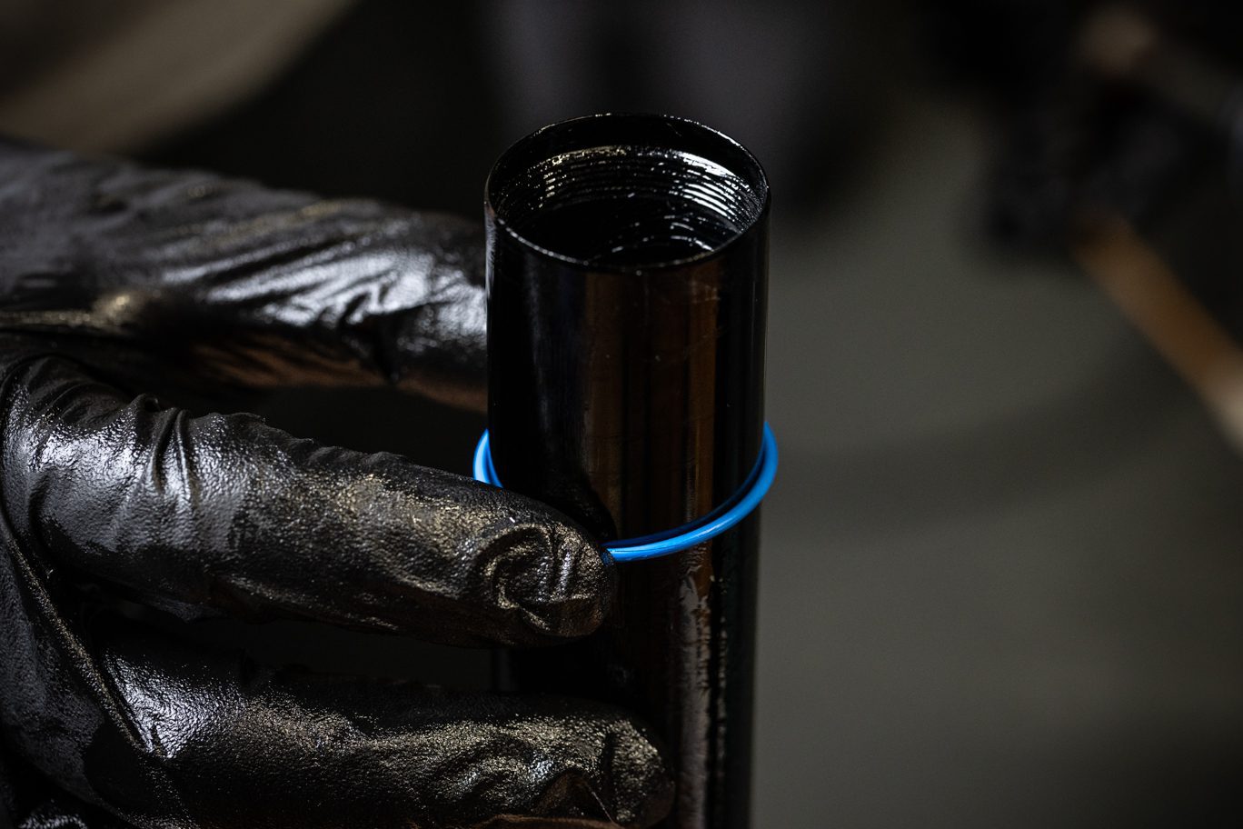
Install sag o-ring (AAG0408) on spring side stanchion. Grease interior of stanchion, seal head o-ring and spring perch. Insert compression rod assembly into spring side stanchion. Thread coil seal head into stanchion and torque to 16 NM using 22mm crowfoot.
Sag O-Ring Install
Greasing Spring Stanchion
Greasing Spring Perch
Greasing Seal Head O-Ring
Comp Rod Assembly Install 1
Comp Rod Assembly Install 2
Seal Head Torque
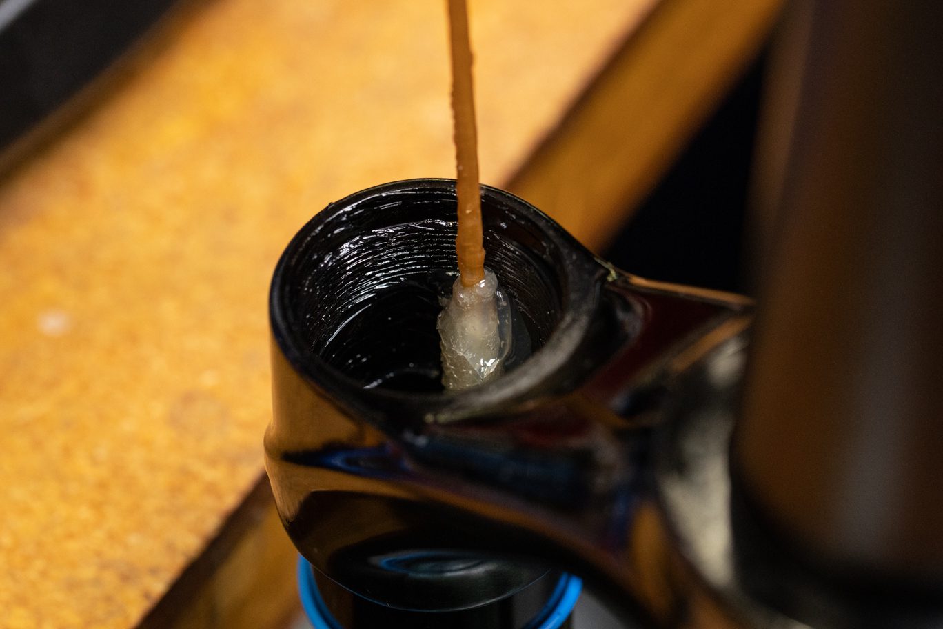
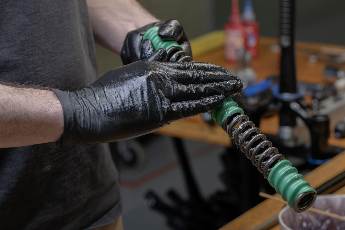
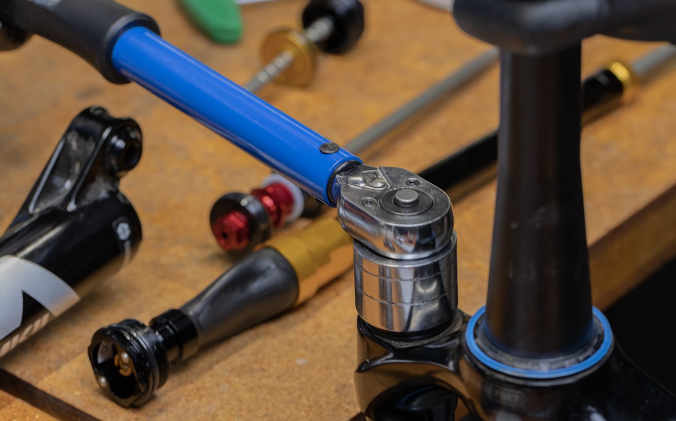
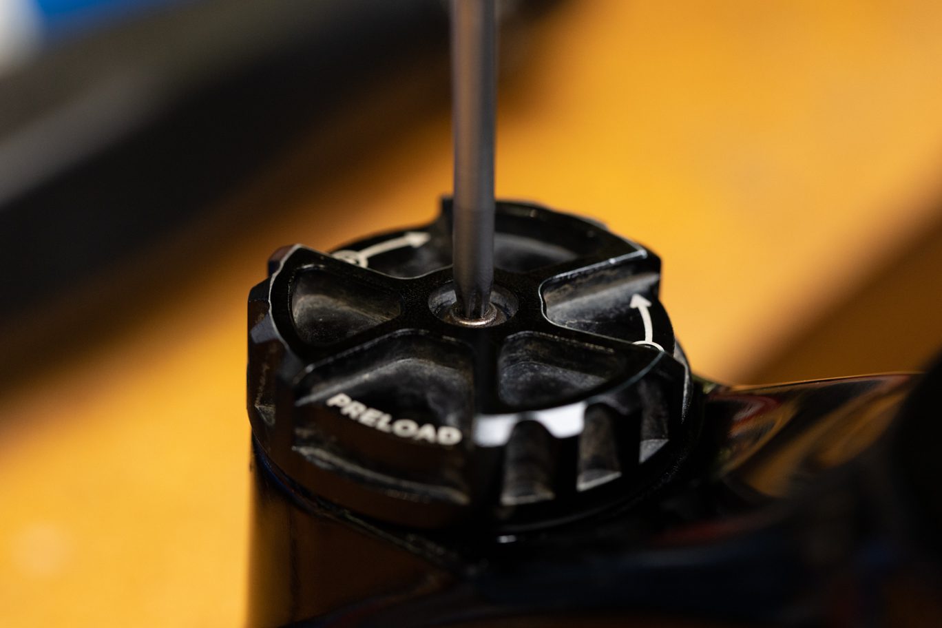
Step 3 – Preloader Assembly Install
Flip CSU. Apply fresh grease to spring. Install spring back into spring side stanchion. Thoroughly clean preloader assembly and check for free movement of preloader. Apply blue Loctite (243) to threads. Install preloader assembly. Torque to 36 Nm using 30mm socket.
Greasing Stanchion Below Threads
Greasing Spring
Spring Install
Cleaning Preload Assembly
Checking Preload Assembly Function
Applying Loctite to Preload Assembly
Preload Assembly Install
Preload Assembly Torque
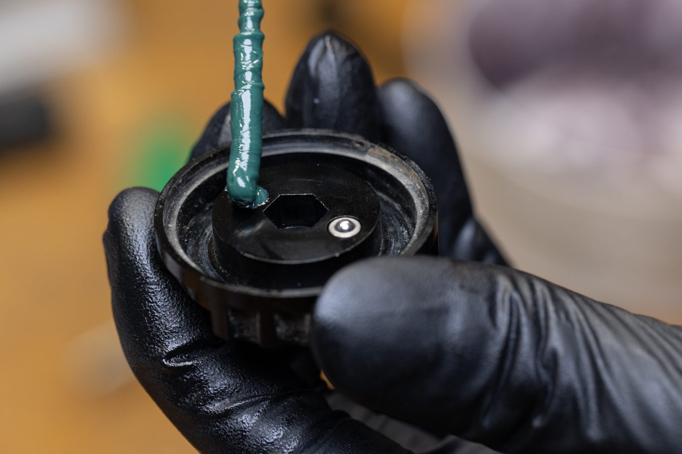
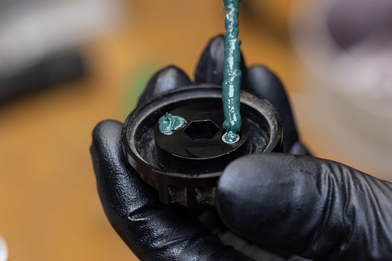
Step 4 – Preloader Cap Install
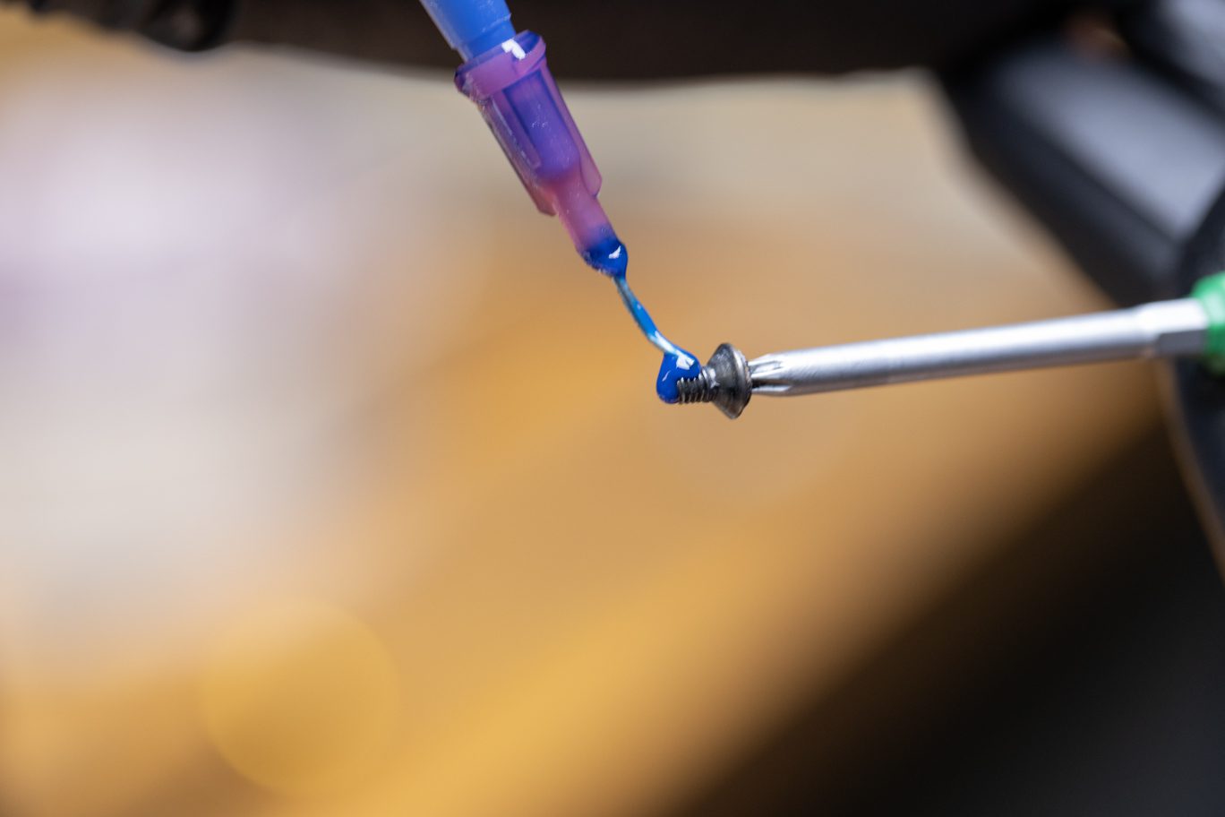
Apply PolyLube to detents on underside of preloader cap. Apply blue Loctite (243) to preloader cap screw. Install preloader cap and screw. Torque to 1.6 Nm with T10.
Greasing Preloader Detent 1
Greasing Preloader Detent 2
Applying Loctite to Preloader Cap Screw
Preloader Cap Install
Preloader Cap Screw Install
Lower Assembly Install
Step 1 – Air Spring Assembly Install
Upon completion of the spring side install and any damper service, install lower assembly per the 50 hour service instructions.
Lowers Install 1