
DBInline Complete 100 Hour Service Instructions (Part 1 of 4)
Jul 2022 orig.
Table of Contents
Recommendations and Warnings
Cane Creek recommends only trained suspension technicians perform service on all suspension, using all required tools and following all proper procedures. Anyone without access to the proper equipment or with any concerns on the procedures should defer to an authorized Cane Creek service center for service. Improper service can result in loss of performance or suspension failure. All Cane Creek shocks have pressurized nitrogen and oil, even coil shocks. Follow the service procedures exactly as written to avoid possible injury or harm to the suspension. Always wear eye protection while performing suspension service.
Please dispose of all waste products and materials through proper channels to avoid contamination of the environment.
Any damage or issues resulting from improper service will not be covered by warranty. If you have a shock still in its original warranty period and do not wish to void your warranty, please contact an authorized Cane Creek service center.
These service instructions cover the basic service procedures using standard service kits. If your suspension requires parts beyond standard replacement parts – shaft, damper tubes, end eyes – please consult your authorized Cane Creek service center or contact us at our Cane Creek Support Center.
Service Notes
As the predecessor of the Air IL, the two shocks share many service steps. Some images in these instructions may not be identical to the valve body or outer damper tube on the Inline, but that is only when the process is the same for the shock in the image and the shock on your bench.
Service Kits
BAD1214 – DBInline/DBair IL Damper Rebuild Kit (Standard)
BAD1185 – DBInline Air Spring Rebuild Kit
AAD1801 – DBInline Purple Fat Quad Piston (if needed)
Required Cane Creek Tools
AAD1101-01 – Keith Cradle
BCD0344 – Kitsuma/DBair/DBair IL Air Seal Head Tool
AAD1193 – Air Seal Head Bullet – Red (or original AAD1182 – Air Seal Head Bullet – Green)
BAD1459 – Air Piston Funnel
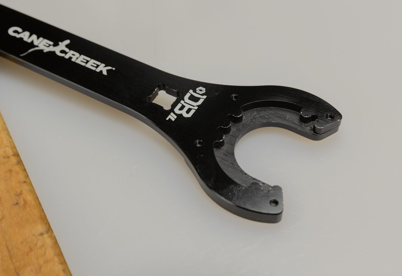
BAD1032 – Gland Nut Wrench
BAD1174 – Oil Seal Head Pin Spanner Wrench
BAD1268 – Inline – Oil Fill Needle Adaptor
DBT016 – DB Gas Fill Needle
AAD0555 – 8mm & 9.5mm Shaft Clamp
BAD1273 – Inner Damper Tube Install Tool (if replacing inner damper tube)
Additional Tools & Supplies
Allen wrenches – 1.5, 3 & 4mm
Torx wrenches – T10, T15 & T25
1/2″ crowfoot wrench
Torque wrenches
Pick
Suspension Grease
Royal Purple 10w-30 Oil
Motorex 4wt Racing Fork Oil
Vacuum Oil Fill Machine
Nitrogen Fill System
Torque, Loctite, Oil & Nitrogen Specs
Torque & Loctite Chart
| Part | Torque Spec | Loctite Spec |
|---|---|---|
| Shaft Bolt | 5 Nm | 243 (Blue) |
| TSN | 0.6 Nm | 668 (Green) |
| Spool Valve | 0.16 Nm | 243 (Blue) |
| Inner Damper Tube | 17 Nm | 263 (Red) |
| Oil Seal Head | 15 Nm | None |
| Gland Nut | 52 Nm | 243 (Blue) |
| Climb Switch Screw | 0.16 Nm | 243 (Blue) |
| Air Piston Screws | 3.2 Nm | 243 (Blue) |
| End Eye | 4.8 Nm | 243 (Blue) |
| Inner Air Can/Air Seal Head | 22.6 Nm | None (PolyLube) |
Oil Chart
| Oil Location | Oil Type | Oil Amount |
|---|---|---|
| Air Can | Royal Purple 10w-30 | 5 mL |
| Damper Fill | Motorex 4wt Racing Fork Oil | Fill to 3 Bars |
Nitrogen Chart
| Nitrogen Location | Nitrogen Pressure |
|---|---|
| Valve Body | 11 - 12 Bars |
General Prep


Clean shock. Record tune if desired. Remove hardware. Remove bushings if replacing. Remove valve cap. Bleed air from shock using shock pump. Be sure to depressurize shock slowly to avoid trapping air in the negative chamber.
Hardware & Bushing Removed
Air Bleed
Air Spring Disassembly


Step 1 – Outer Air Can Removal
Clamp shock in soft jaw vise. Remove air can circlip using a pick. Flip the shock and clamp end eye. Using strap wrench, twist and apply downward force to free outer air can. Work outer air can past end eye to remove completely. Note any air volume reduction.
Freeing Air Can Circlip
Air Can Circlip Removal
Strap Wrench on Air Can
Air Can Removal


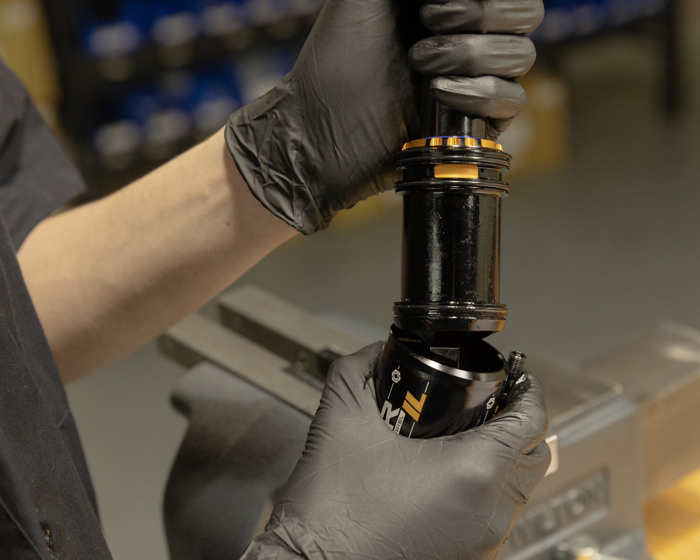
Step 2 - Freeing Inner Air Can
Reclamp shock. Align teeth on Air Seal Head Tool (BAD1273) with grooves on air seal head. Unthread air seal head/inner air can from end eye. Splash oil may be present. Slide inner air cap up shock body to expose shaft.
Clamped for Inner Air Can Freeing
Air Seal Head Wrench IL End
Air Seal Head Tool on Air Seal Head
Air Seal Head Tool Supported
Inner Air Can Freed


Step 3 - End Eye Removal
Slide inner air can up shock body to expose shaft. Clamp shaft in 8mm shaft clamp with end eye up. Remove end eye using 1/2″ crows foot. Pinch & remove then discard inner can o-ring and stop shim from end eye. Remove any stroke reduction spacer, shim and bottom out bumper.
Always use extreme caution when using a pick in this step or others to avoid scratching metal parts. Failure to do this can create scratches in the o-ring glands which cause leak paths for oil or gas. When possible, pinch and remove o-rings rather than using a pick.
TSB004 – DBInline Stop Shim
Clamped for End Eye Removal
Freeing End Eye
End Eye Removed
End Eye O-Ring Removal
Stop Shim Removal
Stroke Reduction & Bottom Out Bumper Removal


Step 4 - Air Piston Removal
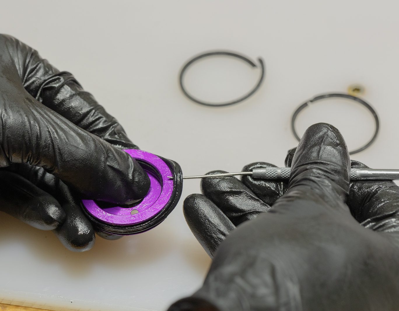
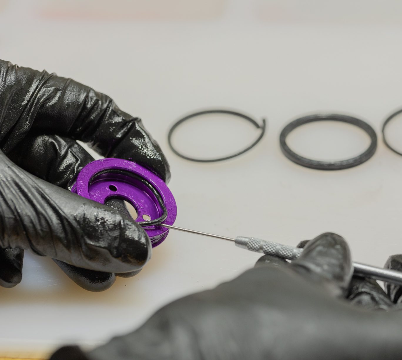
Using T10 loosen and slowly remove all 3 air piston screws. Use caution as this will release any air trapped in negative chamber. Pull up on inner air can to remove inner air can and piston. Press piston out of inner air can. If piston is red, discard. If purple, remove 2 L-back up rings, quad ring and interior o-ring from piston and discard.
TSB008 – DBInline Fat Quad Air Piston
Air Piston Set Screw Removal (old piston)
Air Piston Set Screws
Air Piston Set Screw Removal
Air Piston Set Screw Removed
Inner Air Can & Piston Removed
Pressing Piston out of Air Can
Air Piston Removal (old piston)
Piston L-Ring Removal
Piston Quad-Ring Removal
Piston O-Ring Removal
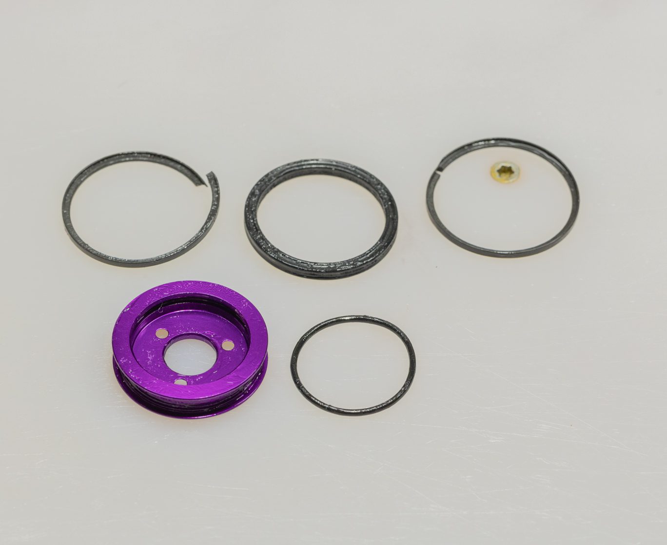
Air Piston Disassembled


Step 5 – Inner Air Can Disassembly
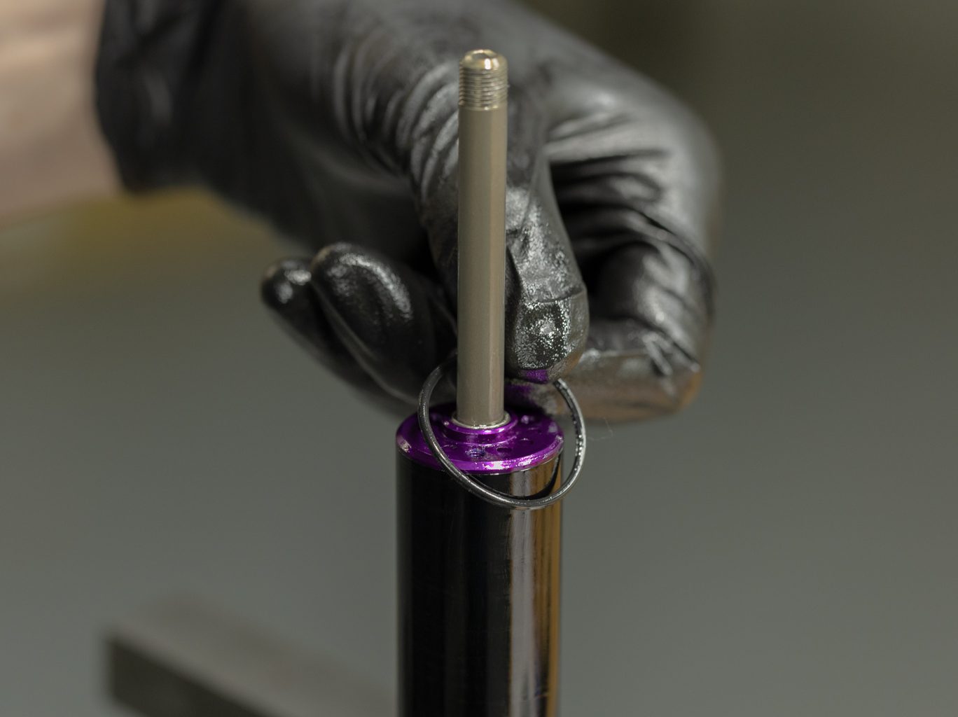
Remove both o-rings and blue wiper seal from inner air can. Remove 2 L-back up rings and quad ring from interior of inner air can. Remove sag o-ring. Discard all rings, seals and wiper. Inspect inner air can for wear. Replace as necessary.
Inner Air Can Wiper Seal Removal
Inner Air Can O-Ring Removal
Inner Air Can Back Up Ring Removal
Inner Air Can Quad Ring Removal
Sag O-Ring Removal
Inner Air Can Inspection
Damper Disassembly


Step 1 – Climb Switch Removal
Loosen 1.5mm set screw. Remove Climb Switch. Pry off oil fill screw cover.
Climb Switch Removal
Climb Switch Removal (close up)
Fill Cover Removal 1
Fill Cover Removal 2
Fill Cover Removed


Step 2 – Nitrogen Bleed
***Use caution as nitrogen is pressurized.***
Loosen gas fill cover half a turn with 4mm Allen. Bleed gas with gas fill needle. Remove gas fill cover completely. Use pick to pry out gas fill plug.
Always use extreme caution when using a pick in this step or others to avoid scratching metal parts. Failure to do this can create scratches in the o-ring glands which cause leak paths for oil or gas.
Backing Off Fill Cover
Fill Cover Backed Off
Degassing Valve Body
Removing Gas Fill Cover
Removing Fill Plug
Gas Fill Plug Removed


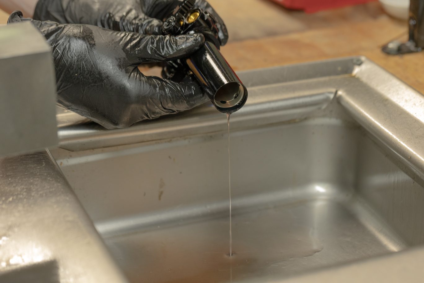
Step 3 – Oil Removal
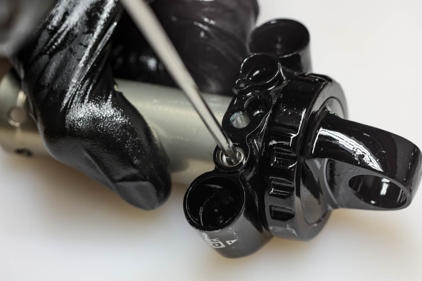
Remove oil fill screw with T15.
***Use caution as there may be aerated oil behind fill screw.***
Empty oil through fill screw by cycling the damper.
Fill Cover Removed
Removal of Oil Fill Screw 1
Removal of Oil Fill Screw 2
Cycling Oil From Valve Body
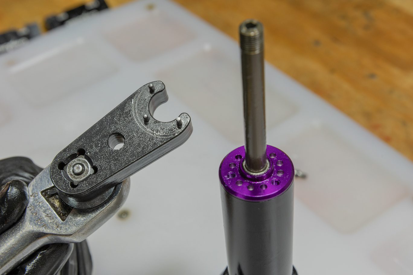


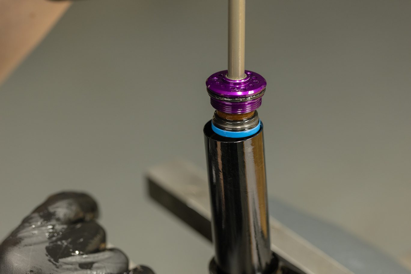


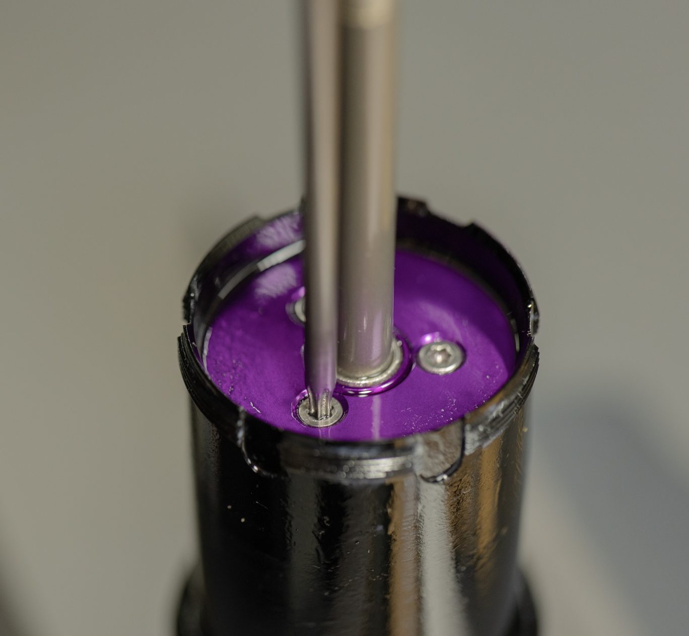
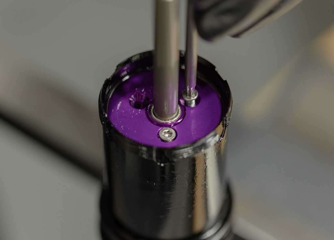
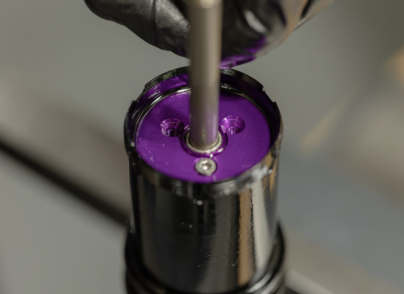
Step 4 – Oil Seal Head & Shaft Assembly Removal
Clamp shock valve body in vise. Use Oil Seal Head Pin Spanner (BAD1174) to free oil seal head. Remove shaft assembly from damper body. Pour out any remaining oil from damper body. Remove outer damper tube.
TSB007 – DBInline Fat Quad Oil Seal Head
Oil Seal Head Pin Spanner
Freeing Oil Seal Head (old seal head)
Oil Seal Head Pin Spanner on Oil Seal Head
Oil Seal Head Freed
Shaft Assembly Removal
Shaft Assembly Removal (old seal head)
Oil Disposal
Removing Outer Damper Tube


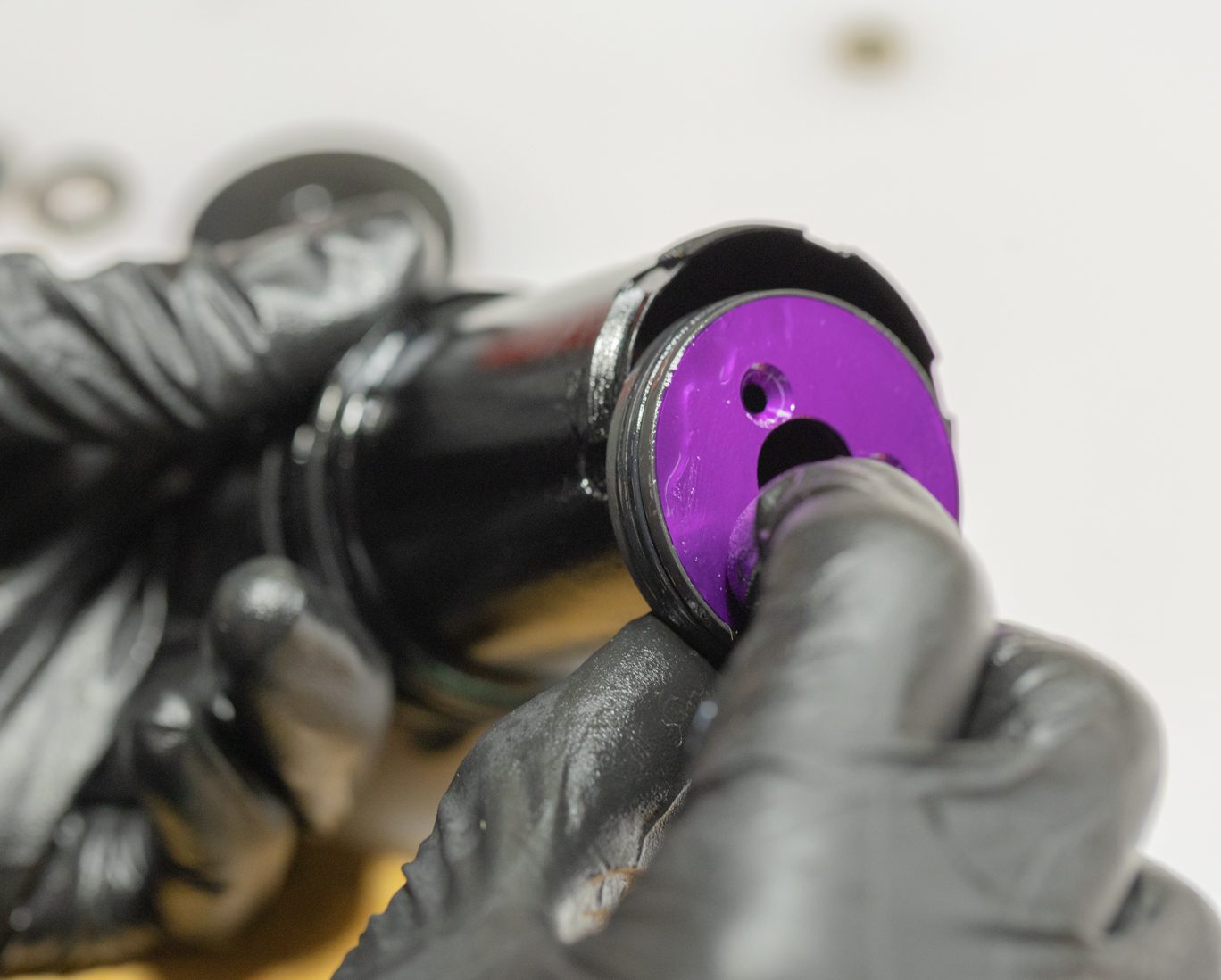
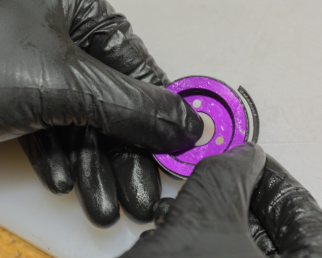
Step 5a – Inner Damper Tube Inspection
Inspect inner damper tube for piston band wear. Remove outer damper tube o-ring with pick and discard.
Inner Damper Tube Inspection 1
Inner Damper Tube Inspection 2
Outer Damper Tube O-Ring Removal 1
Outer Damper Tube O-Ring Removal 2
Outer Damper Tube O-Ring Removal 3

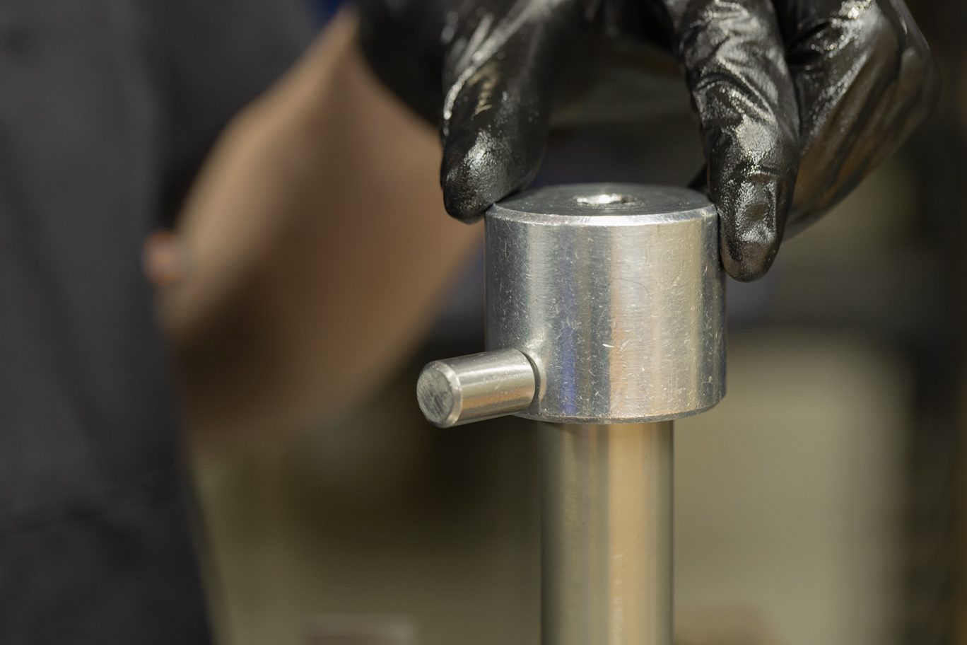


Step 5b – Inner Damper Tube Removal (if needed)
Using Inner Damper Tool Wrench (BAD1273), remove inner damper from valve body. Inspect damper tube threads and remove any remaining Loctite with pick. Clean thoroughly if not replacing. Remove valve body o-ring and discard.
Attaching Inner Damper Tube Tool Wrench
Inner Damper Tube Tool Wrench Attached
Freeing Inner Damper Tube
Removing Inner Damper Tube
Removing Valve Body O-Ring


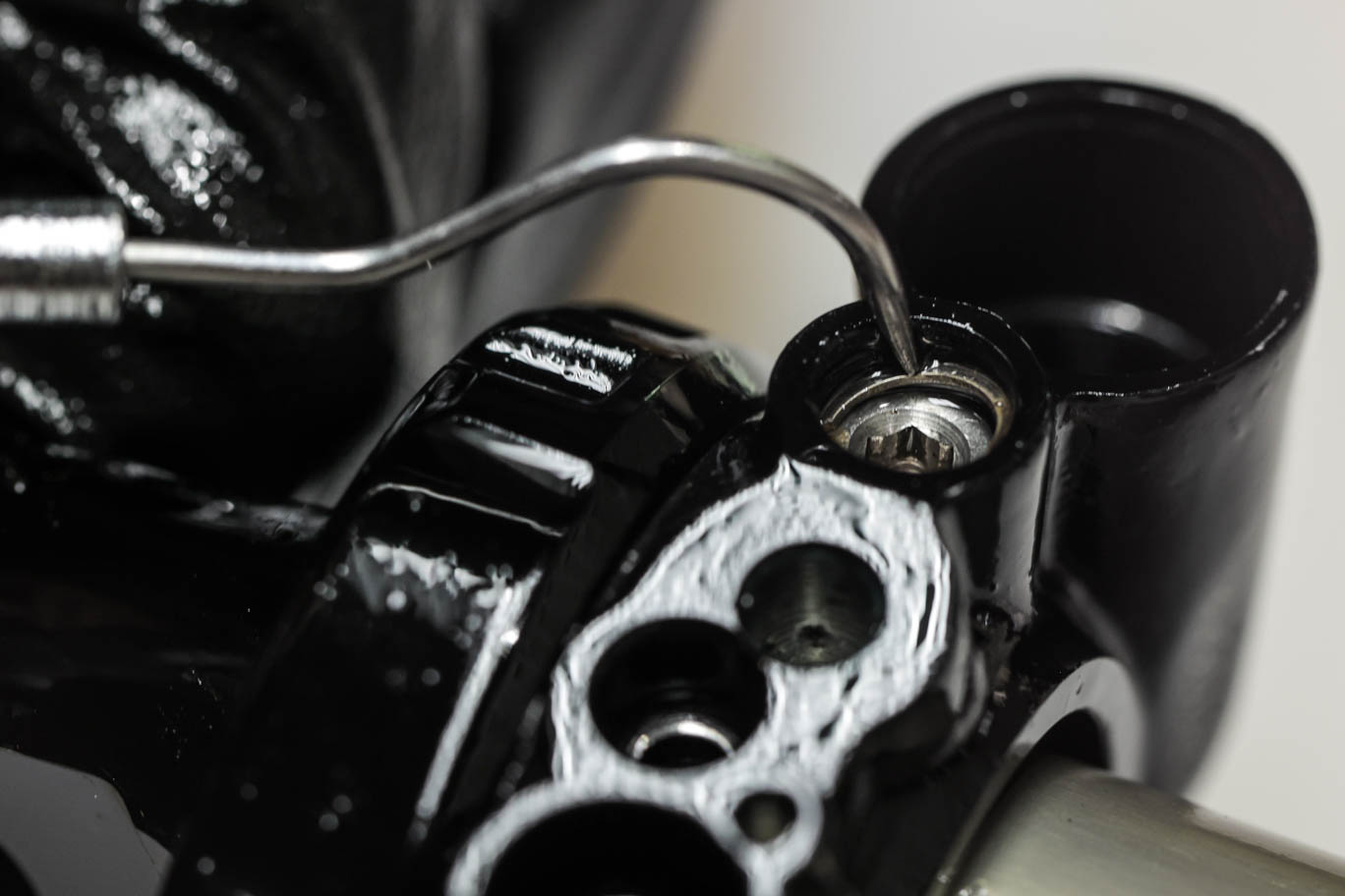
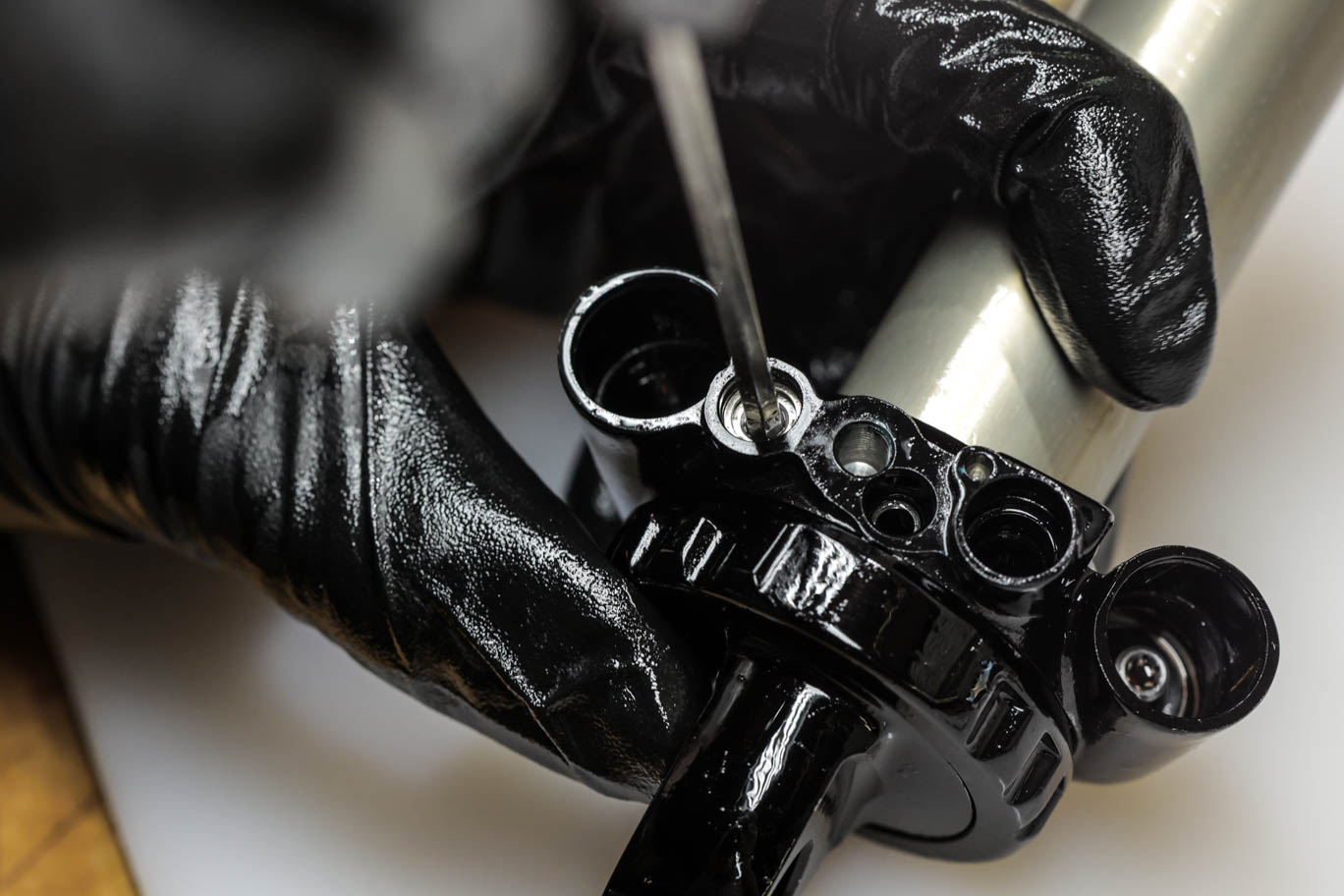
Step 6 – High Speed Adjusters Removal
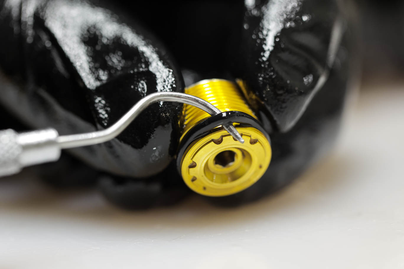
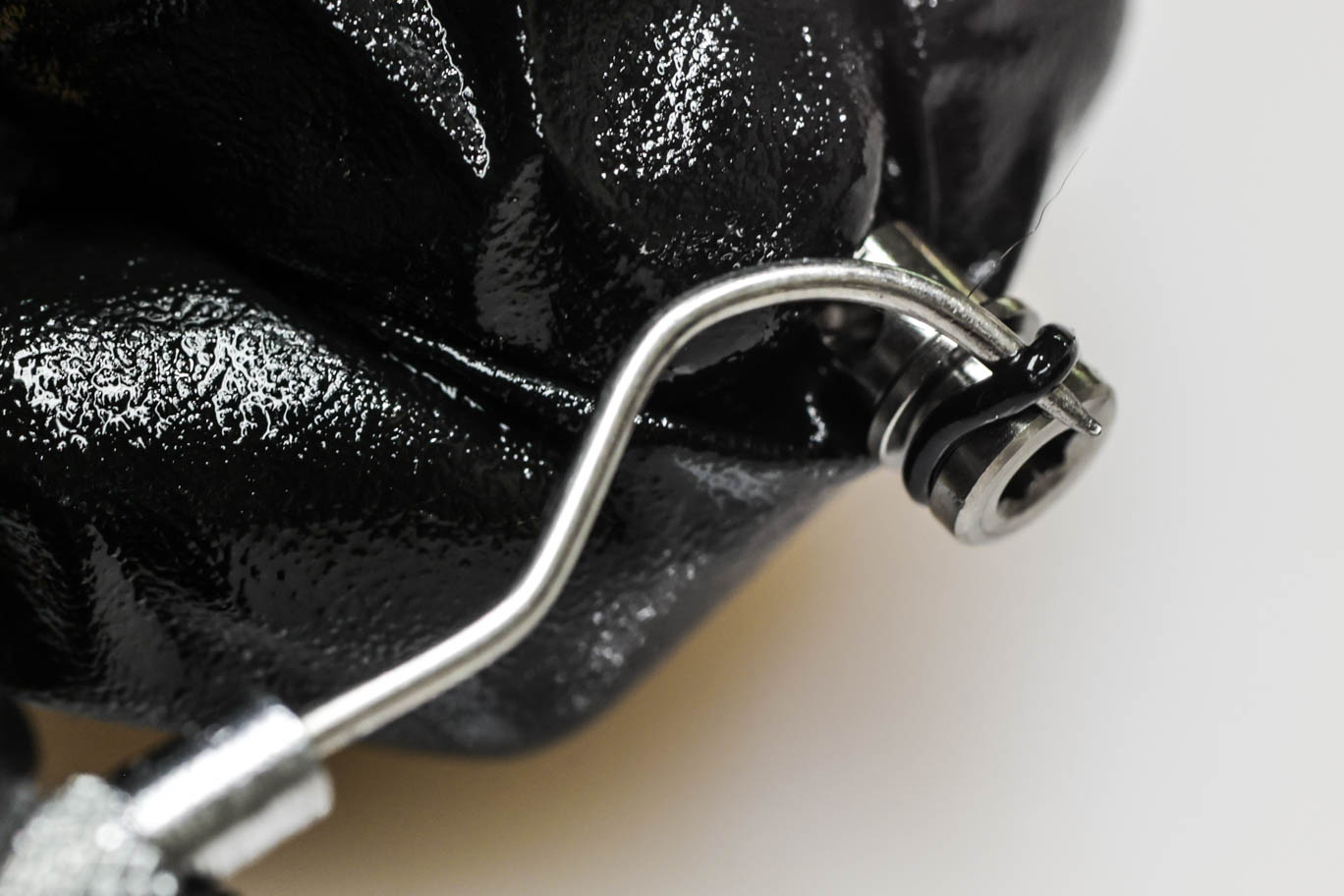
Unthread spool valve capture screw with 1.5mm Allen. Using 3mm Allen, dial High Speed adjusters in to gain access to High Speed circlips. Remove circlips. Back High Speed adjusters all the way out. Remove and discard o-rings on adjusters.
Note that the Compression spring is 20wt (silver), rebound is 30wt (black).
Unthreading Spool Valve Capture Screw
Dialing In High Speed Adjusters
Circlip Removal from High Speed Adjusters
Circlips Removed
Removing High Speed Adjusters
High Speed Compression Adjuster
High Speed Rebound Adjuster
High Speed Adjuster O-Ring Removal


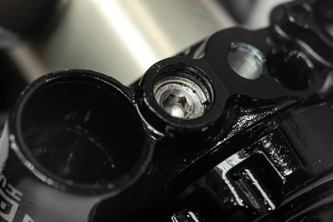
Step 7 – Low Speed Compression Adjuster Removal
Unthread Low Speed Compression needle on spool valve with 3mm Allen and remove. Remove and discard o-rings on needle. Depress spool valve detent with razor blade to free spool valve. Remove detent and unthread spool valve. Remove and discard spool valve o-ring.
Low Speed Compression Needle Removal
Low Speed Compression Needle Removed
Low Speed O-Ring Removal
Depressing Spool Valve Detent 1
Depressing Spool Valve Detent 2
Spool Valve Detent Removal
Spool Valve Removal
Spool Valve O-Ring Removal
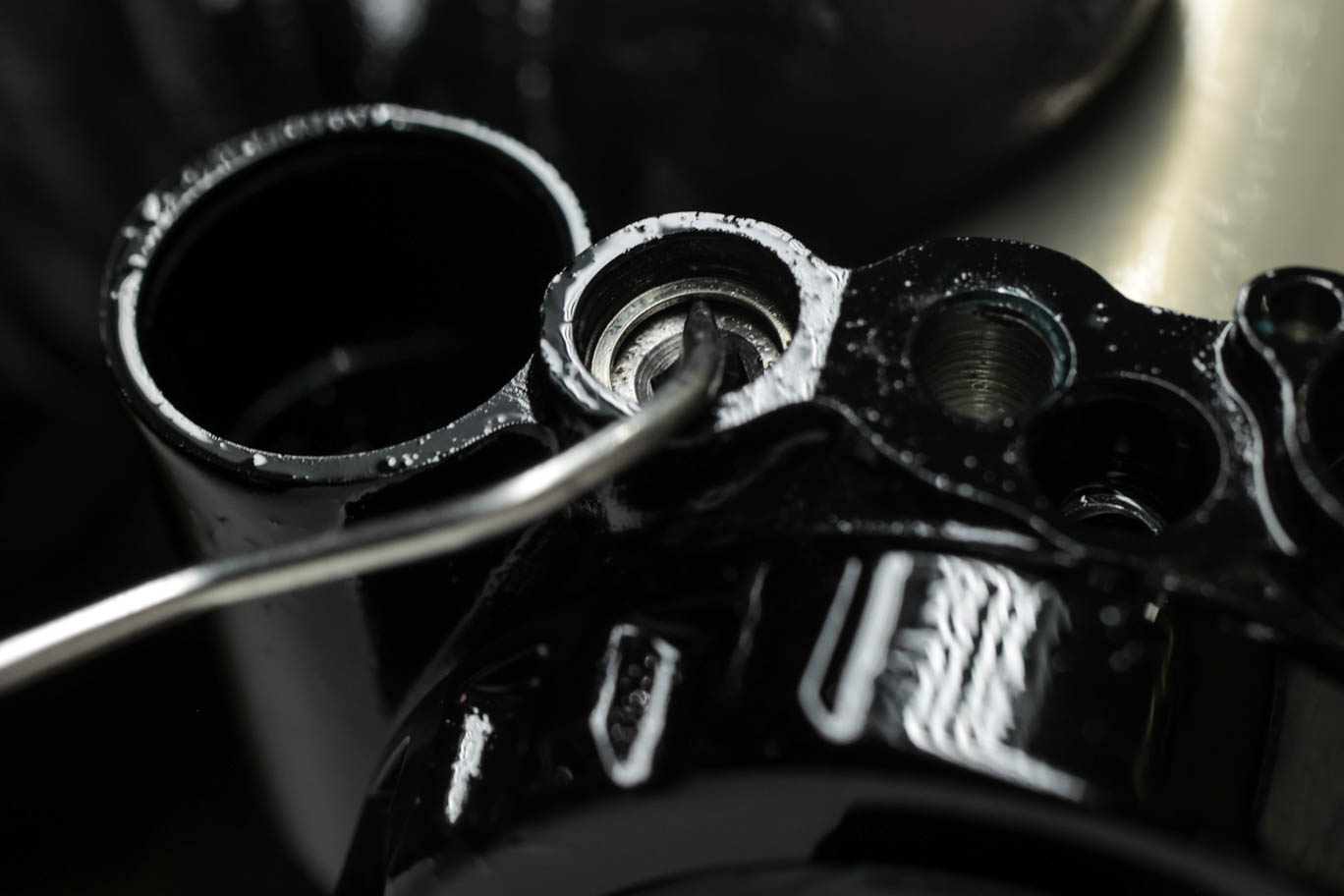
Step 8 – Low Speed Rebound Adjuster Removal
Gently bottom out Low Speed Rebound needle with 3mm Allen. Using pick, work circlip below retaining shelf all the way to needle. Back needle out 5-7 clicks and then rebottom needle to gain access to circlip. Using pick centered on circlip, pry up diagonally to pull circlip past shelf and remove. Unthread and remove needle. Remove and discard o-ring.
Low Speed Rebound Bottom Out
Low Speed Rebound Circlip Removal 1
Low Speed Rebound Circlip Removal 2
Low Speed Rebound Circlip Removal 3
Low Speed Rebound Circlip Removal 4
Low Speed Rebound Needle Removal
Low Speed Rebound Needle O-Ring Removal


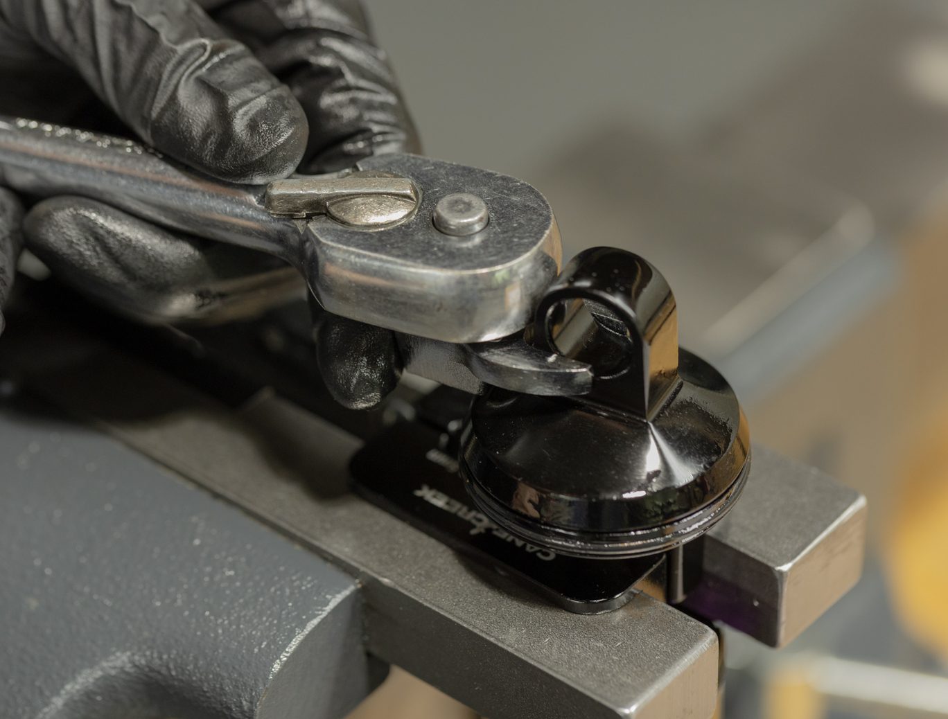
Step 9 – End Eye Removal
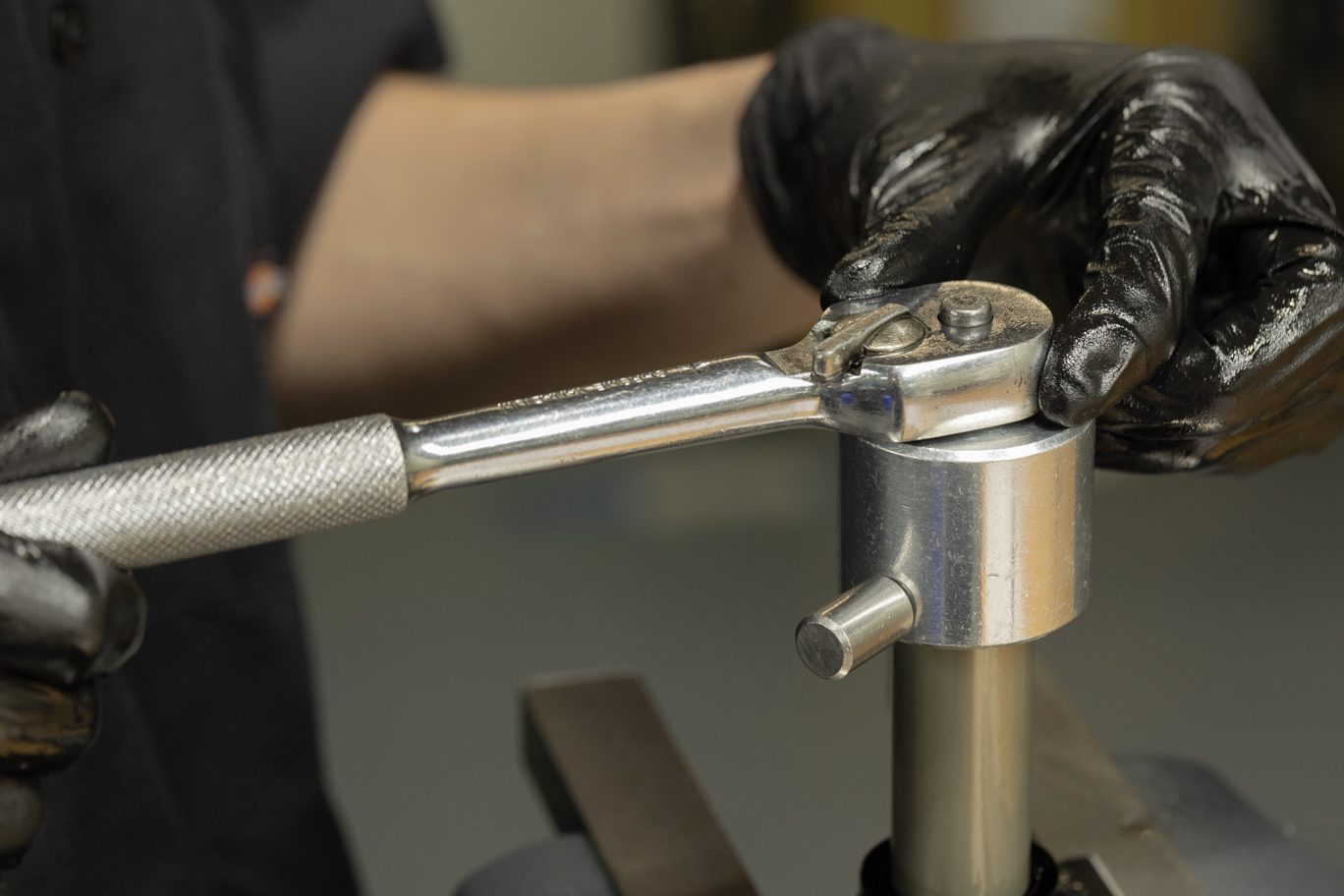
Clamp valve body using Keith Cradle (AAD1101-01). Use Gland Nut Wrench (BAD1032) to free gland nut. Remove end eye. Carefully remove and discard bladder.
Valve Body Clamped in Keith Cradle
Freeing Gland Nut
Gland Nut Removal
End Eye Removal
Bladder Removal
Bladder Removed
Continue to Part 2
Next