Air IL Stroke Change
May 2023 orig.
Recommendations and Warnings
Cane Creek recommends only trained suspension technicians perform service on all suspension, using all required tools and following all proper procedures. Anyone without access to the proper equipment or with any concerns on the procedures should defer to an authorized Cane Creek service center for service. Improper service can result in loss of performance or suspension failure. All Cane Creek shocks have pressurized nitrogen and oil, even coil shocks. Follow the service procedures exactly as written to avoid possible injury or harm to the suspension. Always wear eye protection while performing suspension service.
Please dispose of all waste products and materials through proper channels to avoid contamination of the environment.
Any damage or issues resulting from improper service will not be covered by warranty. If you have a shock still in its original warranty period and do not wish to void your warranty, please contact an authorized Cane Creek service center.
These service instructions cover the basic service procedures using standard service kits. If your suspension requires parts beyond standard replacement parts – shaft, damper tubes, end eyes – please consult your authorized Cane Creek service center or contact us at our Cane Creek Support Center.
Service Notes
This service covers changing stroke ONLY on a new Air IL shock. As o-rings are considered new as part of this service, they will not be replaced. If this stroke change is being done on an older shock, a full 100 hour service is recommended.
The stroke change procedure is the same for Standard and Trunnion mount shocks. Images of both are used interchangeably here.
Service Kits
No service kits required. If reducing stroke, 2.5mm stroke reduction pucks (AAD2578) are required.
Required Cane Creek Tools
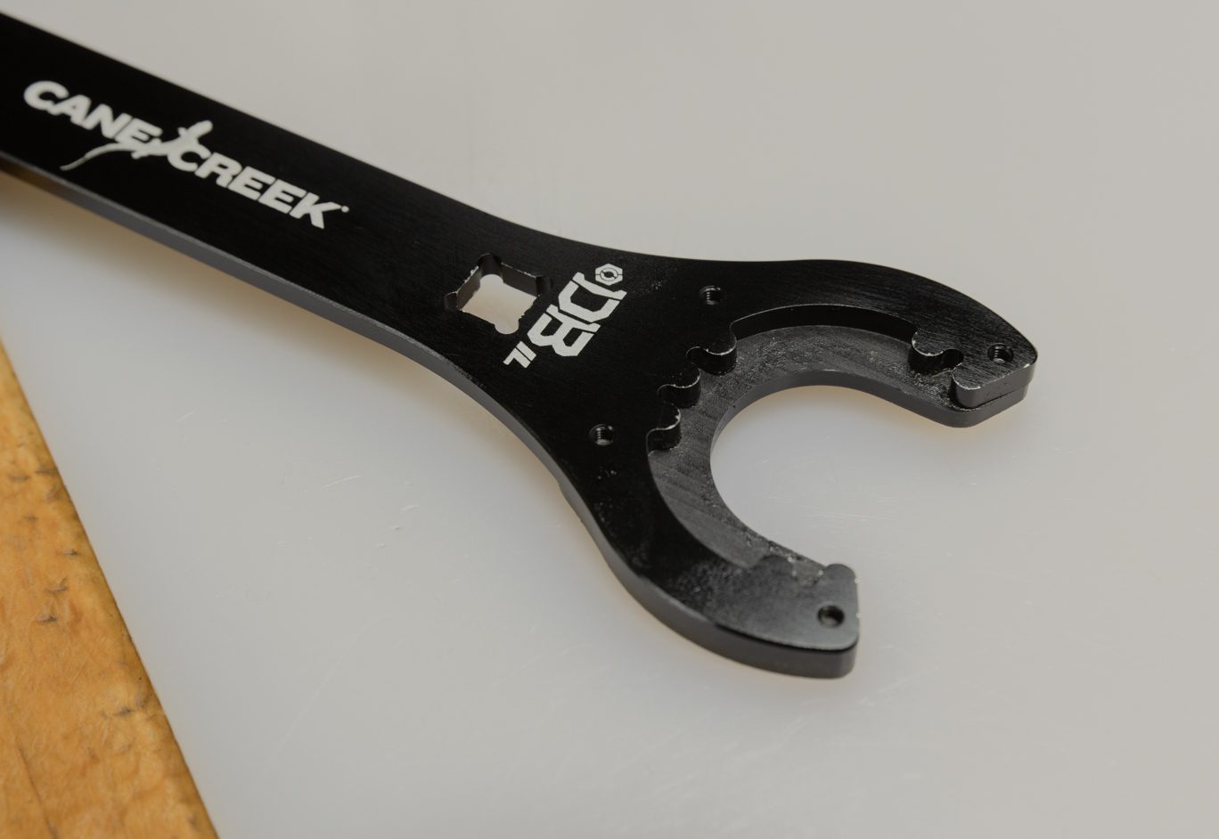
BCD0344 – Kitsuma/DBair/DBair IL Air Seal Head Tool
Additional Tools & Supplies
1/2″ crowfoot wrench
Torque wrenches
Pick
Suspension Grease
Royal Purple 10w-30 Oil
Torque, Loctite, Oil & Nitrogen Specs
Torque & Loctite Chart
Part | Torque Spec | Loctite Spec |
---|---|---|
Inner Air Can/Air Seal Head | 22.6 Nm | None (PolyLube) |
Oil Chart
Oil Location | Oil Type | Oil Amount |
---|---|---|
Air Can | Royal Purple 10w-30 | 5 mL |
General Prep
![](http://b2b.canecreek.com/cdn/shop/files/iLG2-Service-183-of-244_1.jpg?v=1715891579&width=1920)
![](http://b2b.canecreek.com/cdn/shop/files/iLG2-Service-184-of-244_1.jpg?v=1715891602&width=1920)
![](http://b2b.canecreek.com/cdn/shop/files/iLG2-Service-185-of-244_1.jpg?v=1715891623&width=1920)
![](http://b2b.canecreek.com/cdn/shop/files/iLG2-Service-186-of-244_1.jpg?v=1715891622&width=1920)
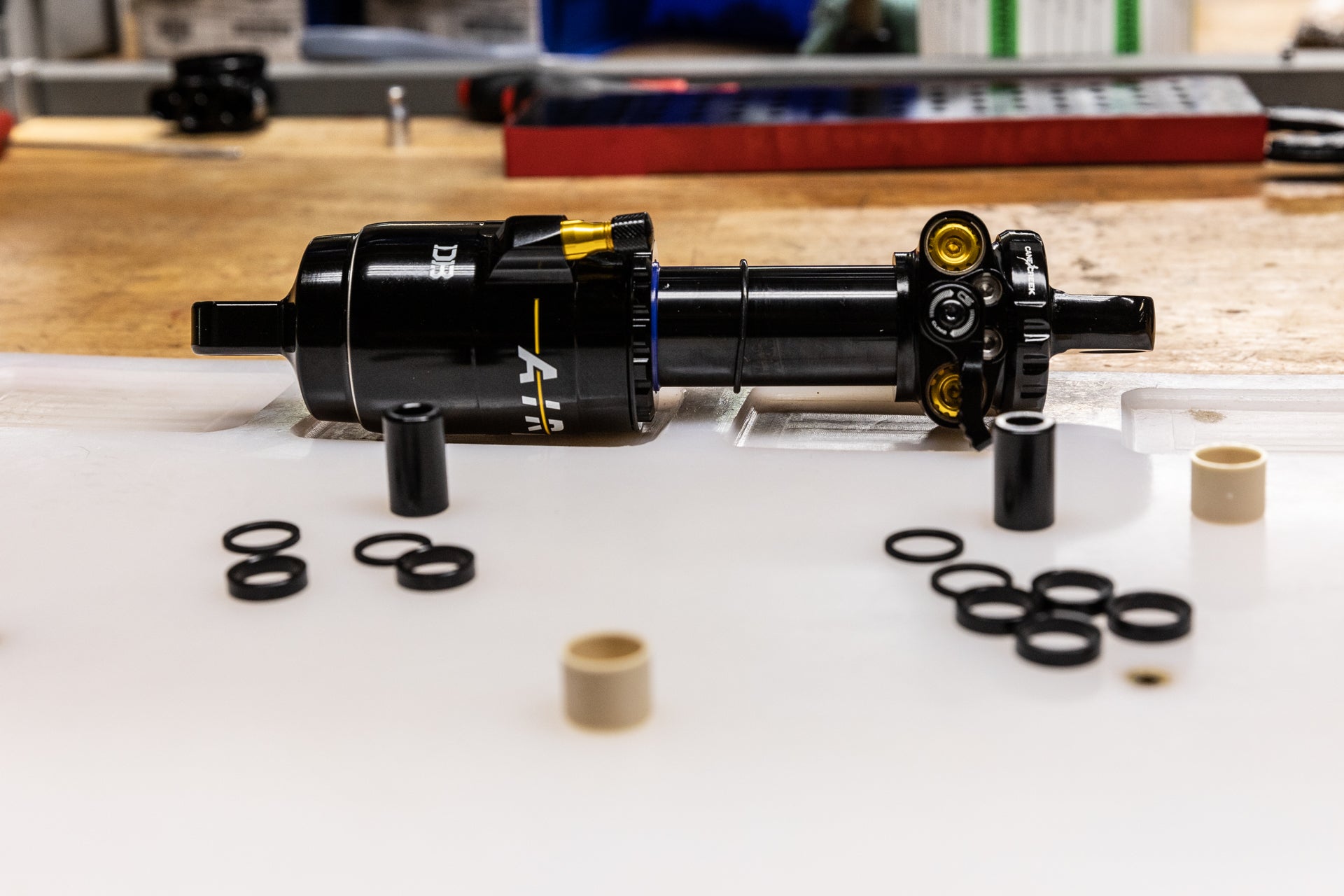
Clean shock. Record tune if desired. Remove hardware. Remove bushings if replacing. Remove valve cap. Bleed air from shock using shock pump. Be sure to depressurize shock slowly to avoid trapping air in the negative chamber.
![](http://b2b.canecreek.com/cdn/shop/files/iLG2-Service-183-of-244_1.jpg?v=1715891579&width=1920)
Hardware & Bushing Removed
![](http://b2b.canecreek.com/cdn/shop/files/iLG2-Service-184-of-244_1.jpg?v=1715891602&width=1920)
Valve Cap Removed
![](http://b2b.canecreek.com/cdn/shop/files/iLG2-Service-185-of-244_1.jpg?v=1715891623&width=1920)
Pump Attach
![](http://b2b.canecreek.com/cdn/shop/files/iLG2-Service-186-of-244_1.jpg?v=1715891622&width=1920)
Air Bleed
Air Spring Disassembly
![](http://b2b.canecreek.com/cdn/shop/files/iLG2-Service-188-of-244_2.jpg?v=1716229236&width=1920)
![](http://b2b.canecreek.com/cdn/shop/files/iLG2-Service-189-of-244_2.jpg?v=1716229251&width=1920)
![](http://b2b.canecreek.com/cdn/shop/files/iLG2-Service-190-of-244_2.jpg?v=1716229374&width=1920)
![](http://b2b.canecreek.com/cdn/shop/files/iLG2-Service-191-of-244_1_176ebf64-371d-4bee-9453-cbd929170e68.jpg?v=1716229516&width=1920)
![](http://b2b.canecreek.com/cdn/shop/files/iLG2-Service-192-of-244_1.jpg?v=1716229535&width=1920)
![](http://b2b.canecreek.com/cdn/shop/files/iLG2-Service-193-of-244_1.jpg?v=1716229555&width=1920)
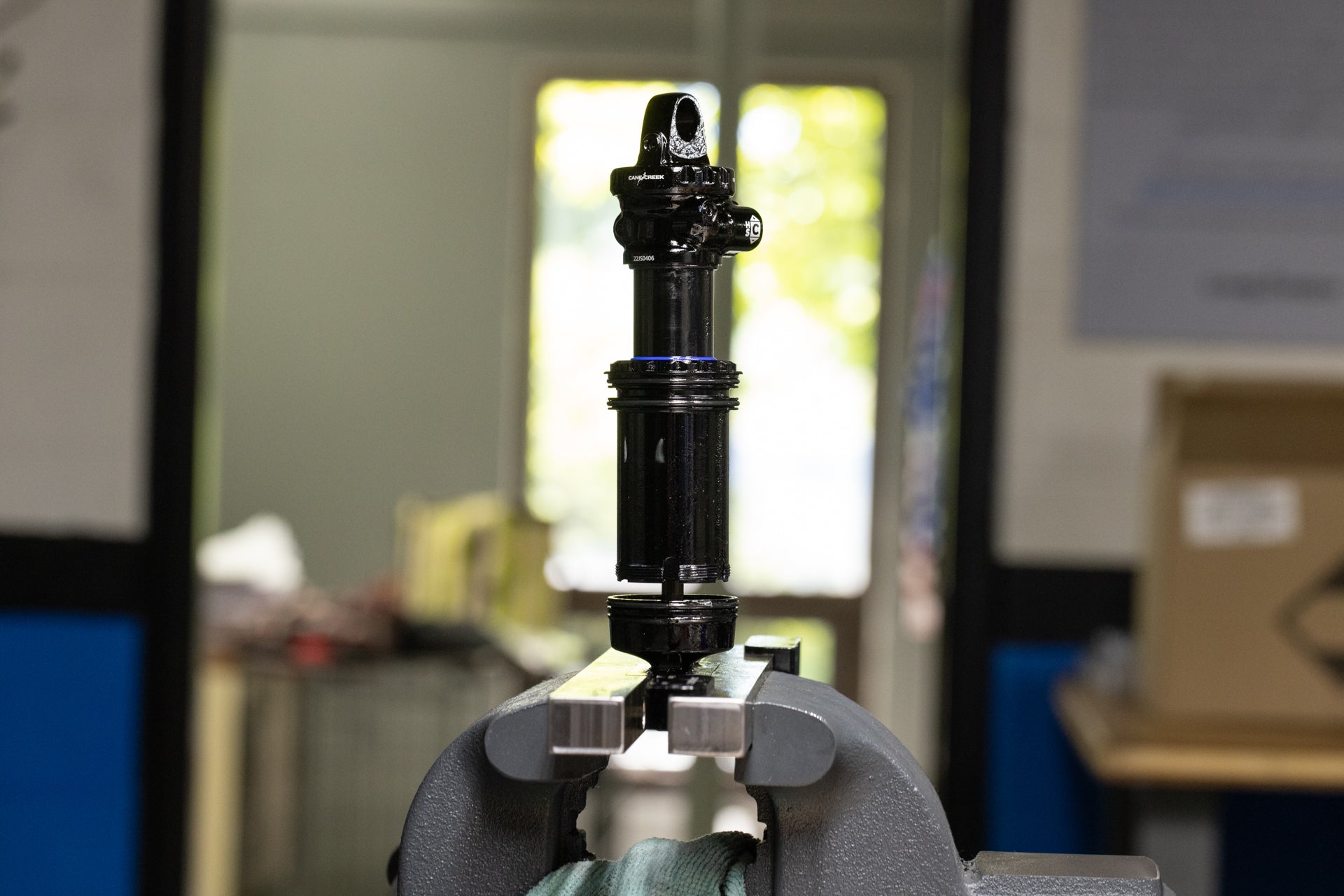
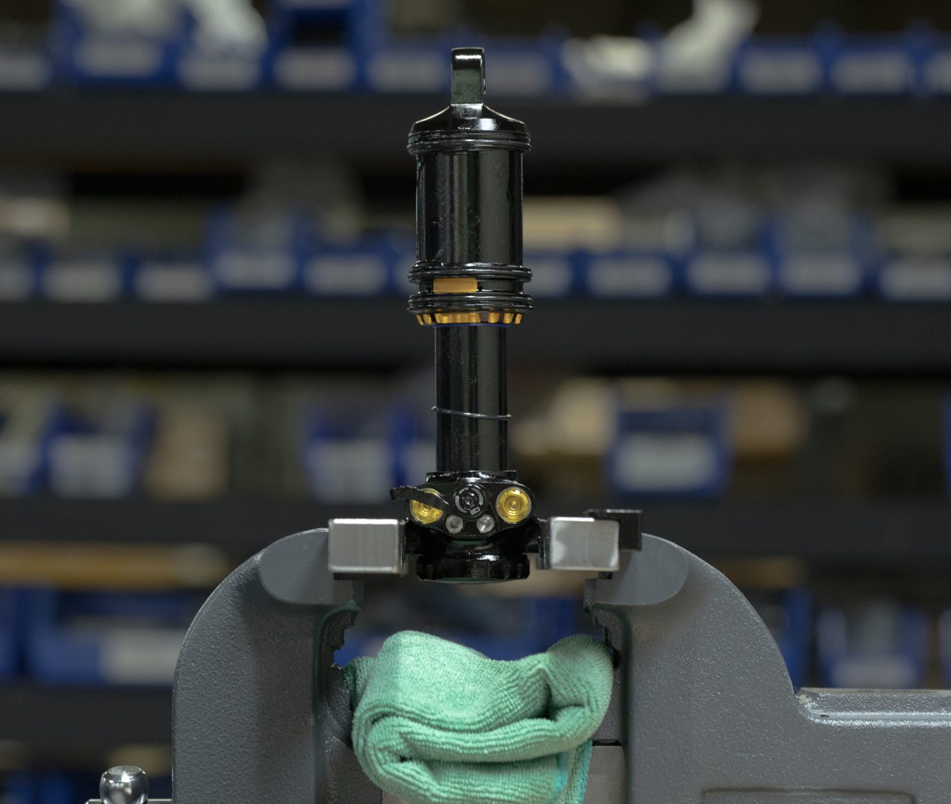
Step 1 – Outer Air Can Removal
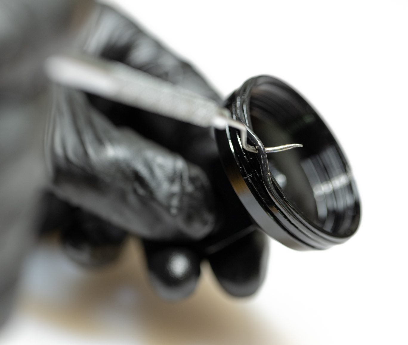
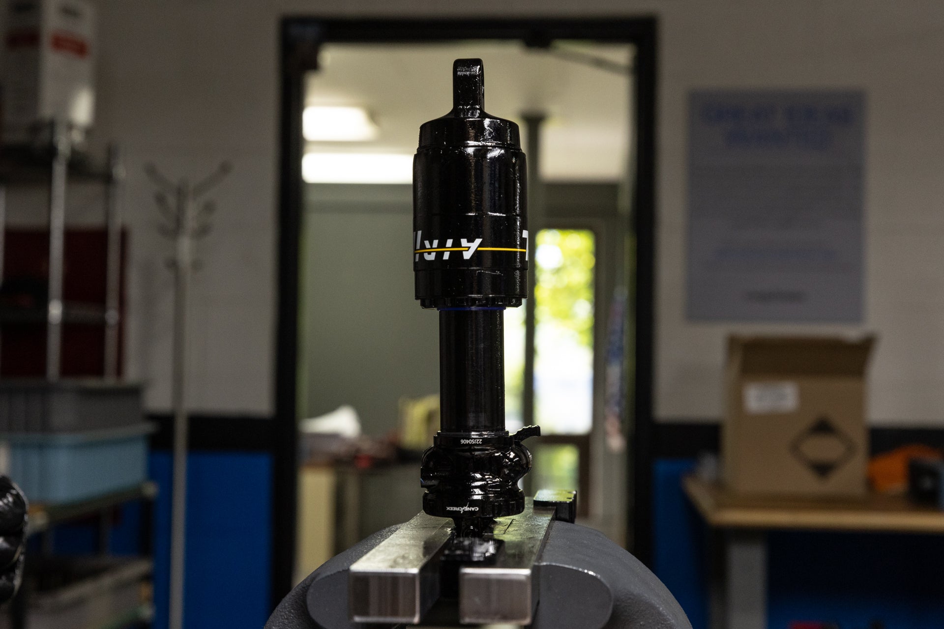
Clamp shock in vise using soft jaws. Remove air can circlip using a pick. Flip the shock in the vise. Using strap wrench, twist and apply downward force to free outer air can. Work outer air can past end eye to remove completely. Note any air volume reduction.
![](http://b2b.canecreek.com/cdn/shop/files/iLG2-Service-188-of-244_2.jpg?v=1716229236&width=1920)
Clamped for Air Can Circlip Removal
![](http://b2b.canecreek.com/cdn/shop/files/iLG2-Service-189-of-244_2.jpg?v=1716229251&width=1920)
Air Can Circlip Removal
![](http://b2b.canecreek.com/cdn/shop/files/iLG2-Service-190-of-244_2.jpg?v=1716229374&width=1920)
Air Can Circlip Removed
![](http://b2b.canecreek.com/cdn/shop/files/iLG2-Service-191-of-244_1_176ebf64-371d-4bee-9453-cbd929170e68.jpg?v=1716229516&width=1920)
Strap Wrench on Air Can
![](http://b2b.canecreek.com/cdn/shop/files/iLG2-Service-192-of-244_1.jpg?v=1716229535&width=1920)
Air Can Freed Past First O-Ring
![](http://b2b.canecreek.com/cdn/shop/files/iLG2-Service-193-of-244_1.jpg?v=1716229555&width=1920)
Air Can Removed
![](http://b2b.canecreek.com/cdn/shop/files/AIR-IL-TRUNNION-2850_1.jpg?v=1716229662&width=1368)
![](http://b2b.canecreek.com/cdn/shop/files/iLG2-Service-195-of-244_1.jpg?v=1716229746&width=1920)
![](http://b2b.canecreek.com/cdn/shop/files/iLG2-Service-194-of-244_1.jpg?v=1716229762&width=1920)
![](http://b2b.canecreek.com/cdn/shop/files/AIR-IL-TRUNNION-2856_1.jpg?v=1716229805&width=1368)
![](http://b2b.canecreek.com/cdn/shop/files/iLG2-Service-196-of-244_1.jpg?v=1716229829&width=1920)
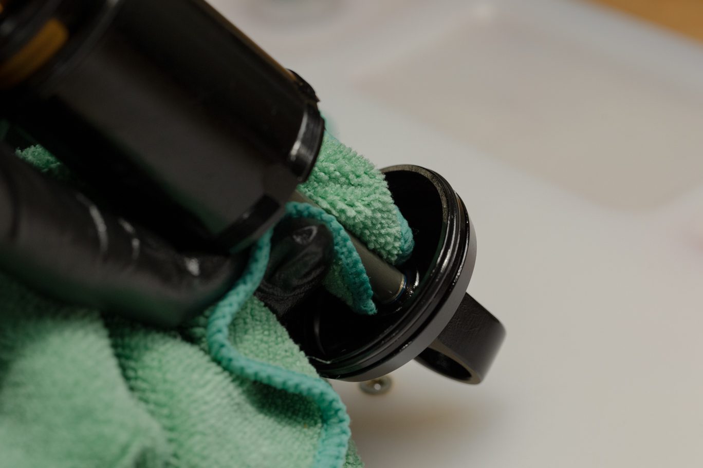
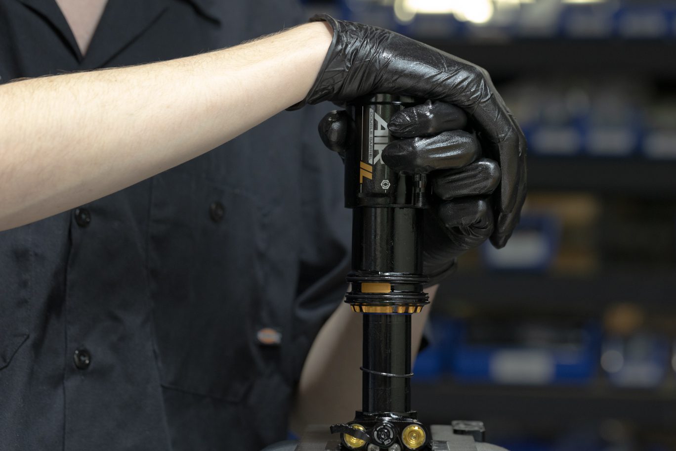
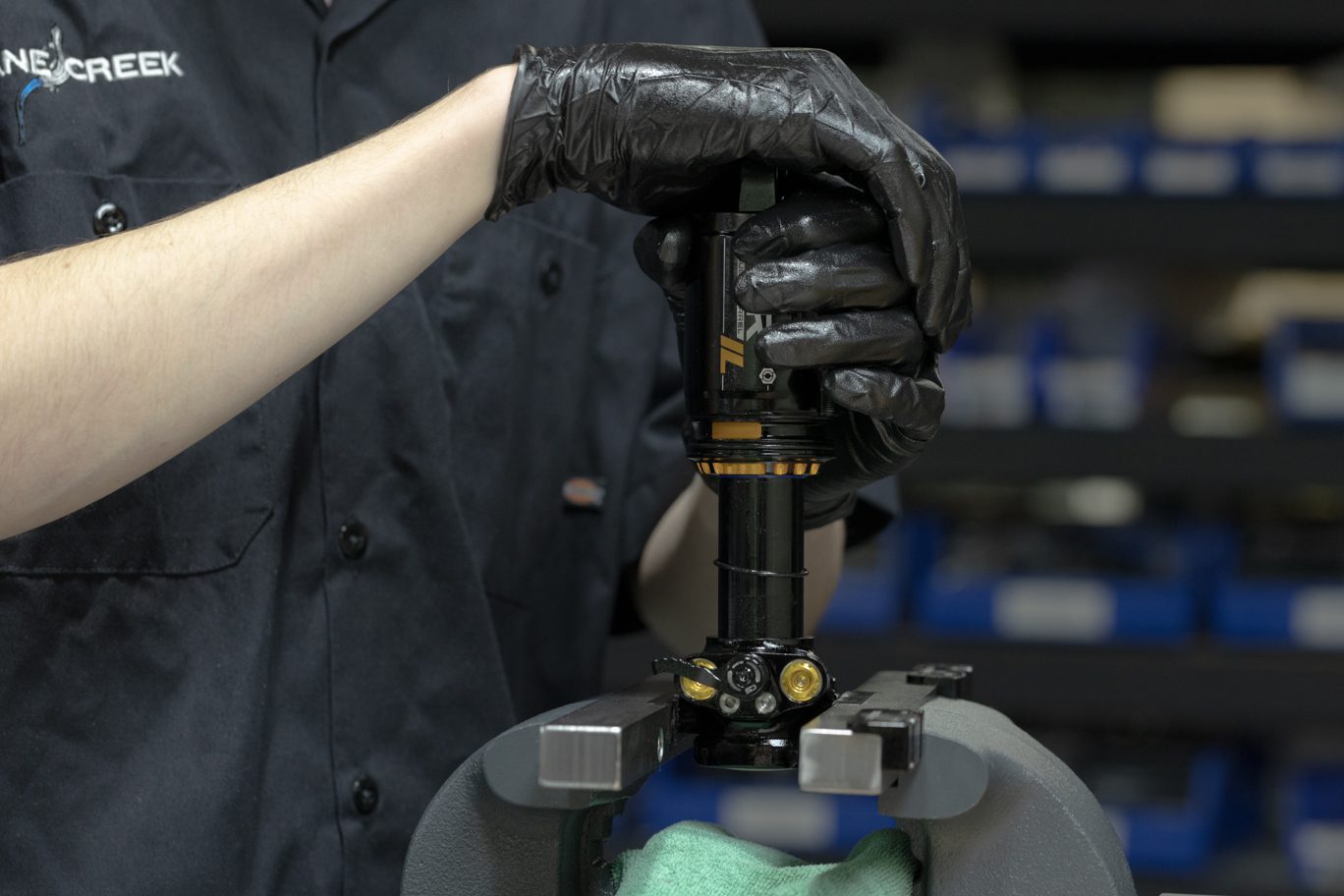
Step 2 - Freeing Inner Air Can
Reclamp shock. Align teeth on Air Seal Head Tool (BAD1273) with grooves on air seal head. Unthread air seal head/inner air can from end eye. Splash oil may be present. Slide inner air cap up shock body to expose shaft.
![](http://b2b.canecreek.com/cdn/shop/files/AIR-IL-TRUNNION-2850_1.jpg?v=1716229662&width=1368)
Air Seal Head Wrench IL End
![](http://b2b.canecreek.com/cdn/shop/files/iLG2-Service-195-of-244_1.jpg?v=1716229746&width=1920)
Air Seal Head Wrench on Air Seal Head
![](http://b2b.canecreek.com/cdn/shop/files/iLG2-Service-194-of-244_1.jpg?v=1716229762&width=1920)
Freeing Inner Air Can from End Eye
![](http://b2b.canecreek.com/cdn/shop/files/AIR-IL-TRUNNION-2856_1.jpg?v=1716229805&width=1368)
Inner Air Can Freed from End Eye 1
![](http://b2b.canecreek.com/cdn/shop/files/iLG2-Service-196-of-244_1.jpg?v=1716229829&width=1920)
Inner Air Can Freed from End Eye 2
![](http://b2b.canecreek.com/cdn/shop/files/iLG2-Service-197-of-244.jpg?v=1716230039&width=1920)
![](http://b2b.canecreek.com/cdn/shop/files/iLG2-Service-198-of-244.jpg?v=1716230068&width=1920)
![](http://b2b.canecreek.com/cdn/shop/files/iLG2-Service-199-of-244.jpg?v=1716230068&width=1920)
![](http://b2b.canecreek.com/cdn/shop/files/AIR-IL-TRUNNION-2866.jpg?v=1716230067&width=1368)
![](http://b2b.canecreek.com/cdn/shop/files/iLG2-Service-202-of-244.jpg?v=1716230068&width=1920)
![](http://b2b.canecreek.com/cdn/shop/files/iLG2-Service-203-of-244.jpg?v=1716230068&width=1920)
![](http://b2b.canecreek.com/cdn/shop/files/iLG2-Service-200-of-244.jpg?v=1716230068&width=1920)
![](http://b2b.canecreek.com/cdn/shop/files/iLG2-Service-201-of-244.jpg?v=1716230068&width=1920)
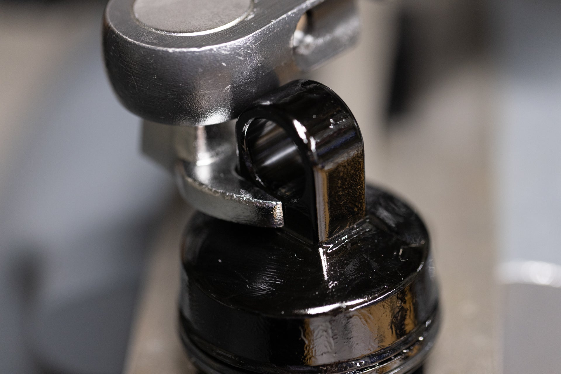
Step 3 - End Eye Removal
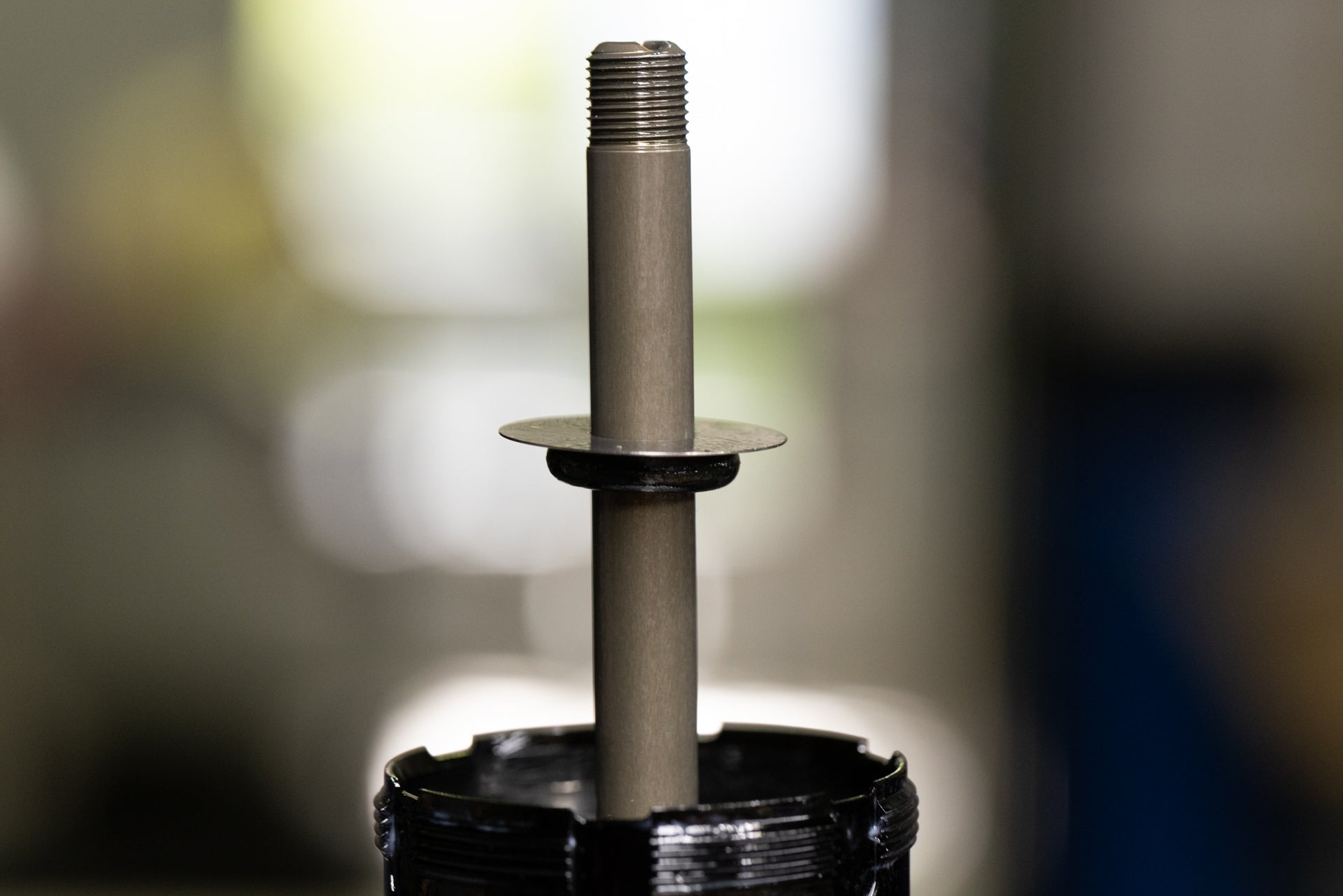
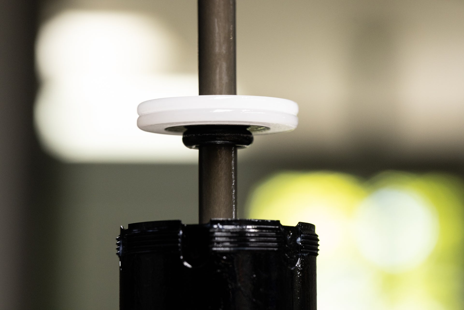
Slide inner air can up shock body to expose shaft. Clamp shaft in 8mm shaft clamp with end eye up. Remove end eye using 1/2″ crows foot. Pinch & remove then discard inner can o-ring and stop shim from end eye. Remove any stroke reduction spacer, shim and bottom out bumper.
Always use extreme caution when using a pick in this step or others to avoid scratching metal parts. Failure to do this can create scratches in the o-ring glands which cause leak paths for oil or gas. When possible, pinch and remove o-rings rather than using a pick.
![](http://b2b.canecreek.com/cdn/shop/files/iLG2-Service-197-of-244.jpg?v=1716230039&width=1920)
Clamped for End Eye Removal
![](http://b2b.canecreek.com/cdn/shop/files/iLG2-Service-198-of-244.jpg?v=1716230068&width=1920)
Freeing End Eye
![](http://b2b.canecreek.com/cdn/shop/files/iLG2-Service-199-of-244.jpg?v=1716230068&width=1920)
End Eye Removed
![](http://b2b.canecreek.com/cdn/shop/files/AIR-IL-TRUNNION-2866.jpg?v=1716230067&width=1368)
End Eye O-Ring Removal
![](http://b2b.canecreek.com/cdn/shop/files/iLG2-Service-202-of-244.jpg?v=1716230068&width=1920)
Stop Shim Removal
![](http://b2b.canecreek.com/cdn/shop/files/iLG2-Service-203-of-244.jpg?v=1716230068&width=1920)
Stop Shim Removed
![](http://b2b.canecreek.com/cdn/shop/files/iLG2-Service-200-of-244.jpg?v=1716230068&width=1920)
Stroke Reduction, Shim & Bottom Out Bumper Removal
![](http://b2b.canecreek.com/cdn/shop/files/iLG2-Service-201-of-244.jpg?v=1716230068&width=1920)
Stroke Reduction, Shim & Bottom Out Bumper Removed
Air Spring Reassembly
![](http://b2b.canecreek.com/cdn/shop/files/iLG2-Service-123-of-244.jpg?v=1724872261&width=1920)
![](http://b2b.canecreek.com/cdn/shop/files/iLG2-Service-124-of-244.jpg?v=1724872294&width=1920)
![](http://b2b.canecreek.com/cdn/shop/files/iLG2-Service-125-of-244.jpg?v=1724872324&width=1920)
![](http://b2b.canecreek.com/cdn/shop/files/iLG2-Service-126-of-244.jpg?v=1724872378&width=1920)
![](http://b2b.canecreek.com/cdn/shop/files/AIR-IL-TRUNNION-3208.jpg?v=1724872415&width=1368)
![](http://b2b.canecreek.com/cdn/shop/files/AIR-IL-TRUNNION-3209.jpg?v=1724872444&width=1368)
![](http://b2b.canecreek.com/cdn/shop/files/iLG2-Service-127-of-244.jpg?v=1724872475&width=1920)
![](http://b2b.canecreek.com/cdn/shop/files/iLG2-Service-128-of-244.jpg?v=1724872510&width=1920)
![](http://b2b.canecreek.com/cdn/shop/files/AIR-IL-TRUNNION-3214.jpg?v=1724872543&width=1368)
Step 1 – End Eye Install
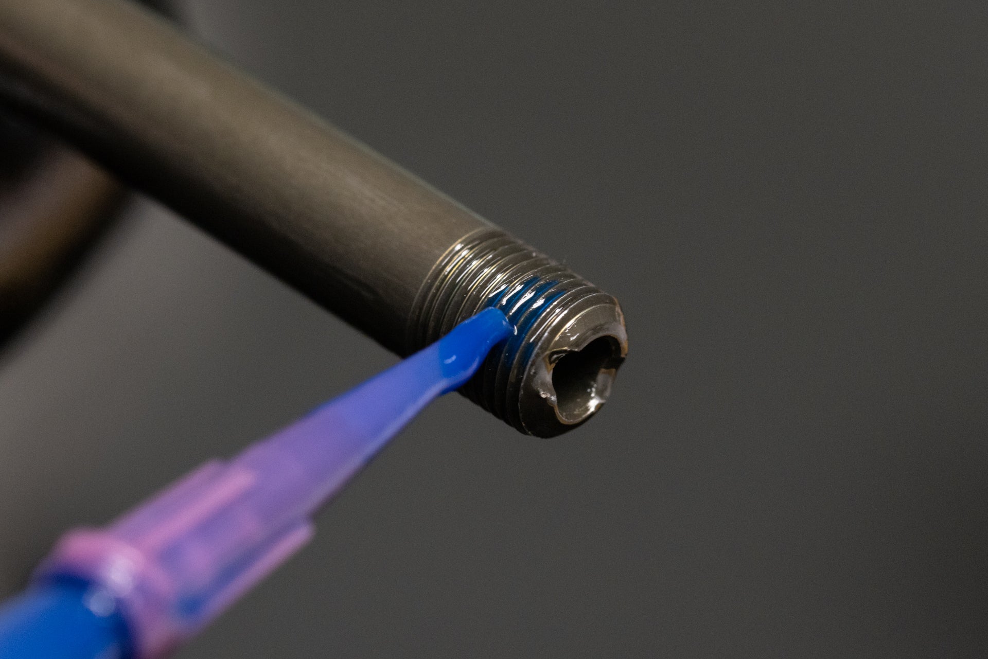
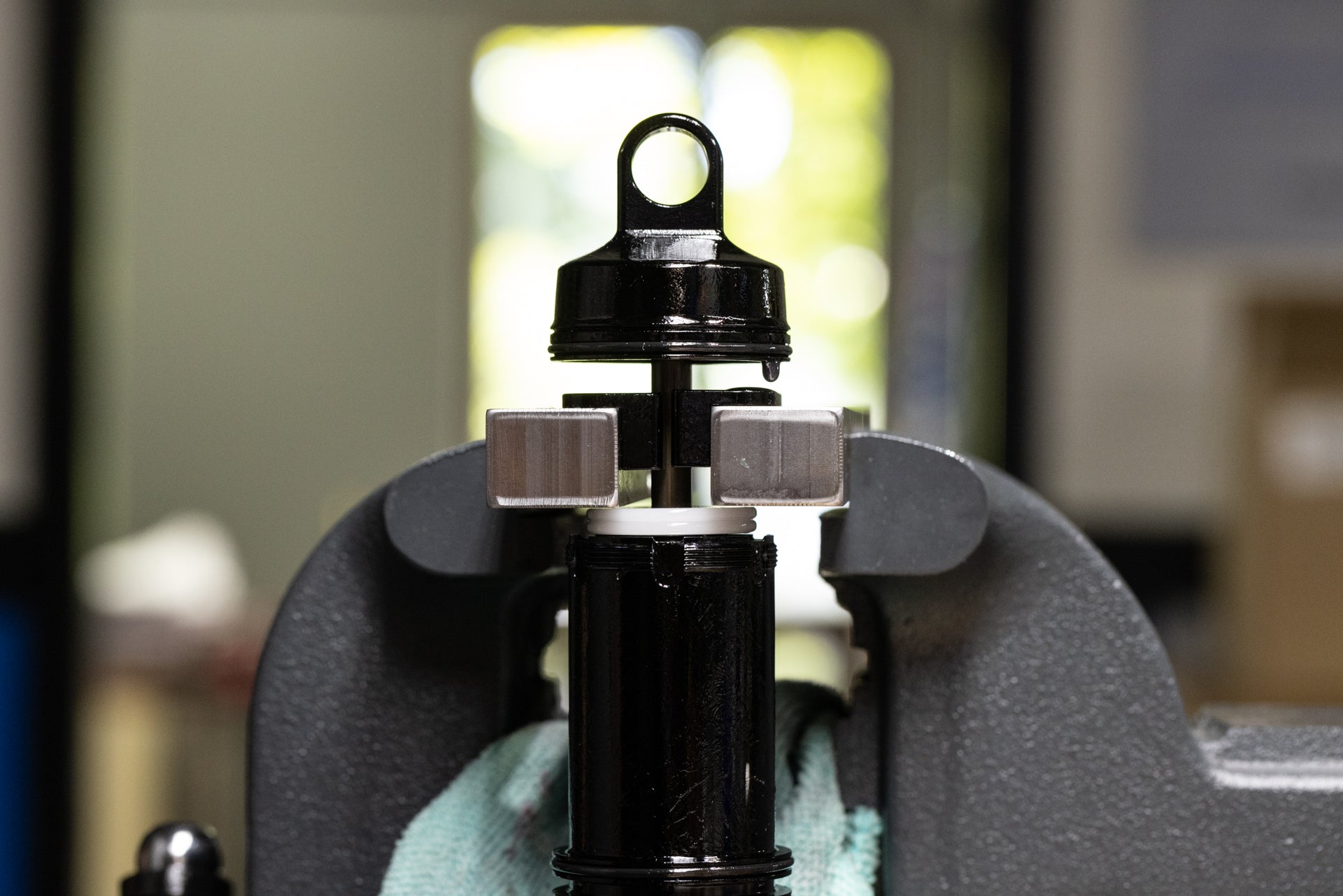
Reinstall bottom out bumper, shim and stroke reduction (if needed). Apply blue Loctite (243) to shaft threads and end eye threads. Thread end eye onto the shaft. Clamp shaft into vise with shaft clamp allowing space for end eye to clear vise when tightened. Using 1/2″ crowsfoot, torque end eye to 4.8 Nm. Clean any extra Loctite from shaft and end eye.
![](http://b2b.canecreek.com/cdn/shop/files/iLG2-Service-123-of-244.jpg?v=1724872261&width=1920)
Bottom Out Bumper Installed
![](http://b2b.canecreek.com/cdn/shop/files/iLG2-Service-124-of-244.jpg?v=1724872294&width=1920)
Shim Installed
![](http://b2b.canecreek.com/cdn/shop/files/iLG2-Service-125-of-244.jpg?v=1724872324&width=1920)
Stroke Reduction Installed
![](http://b2b.canecreek.com/cdn/shop/files/iLG2-Service-126-of-244.jpg?v=1724872378&width=1920)
Applying Loctite to Shaft
![](http://b2b.canecreek.com/cdn/shop/files/AIR-IL-TRUNNION-3208.jpg?v=1724872415&width=1368)
Applying Loctite on End Eye
![](http://b2b.canecreek.com/cdn/shop/files/AIR-IL-TRUNNION-3209.jpg?v=1724872444&width=1368)
Threading Shaft onto End Eye
![](http://b2b.canecreek.com/cdn/shop/files/iLG2-Service-127-of-244.jpg?v=1724872475&width=1920)
Clamping Shaft w/ Ample Space
![](http://b2b.canecreek.com/cdn/shop/files/iLG2-Service-128-of-244.jpg?v=1724872510&width=1920)
Torquing End Eye
![](http://b2b.canecreek.com/cdn/shop/files/AIR-IL-TRUNNION-3214.jpg?v=1724872543&width=1368)
Cleaning Shaft and End Eye of Loctite
![](http://b2b.canecreek.com/cdn/shop/files/iLG2-Service-129-of-244.jpg?v=1724872637&width=1920)
![](http://b2b.canecreek.com/cdn/shop/files/AIR-IL-TRUNNION-3217.jpg?v=1724872674&width=1368)
![](http://b2b.canecreek.com/cdn/shop/files/AIR-IL-TRUNNION-3222.jpg?v=1724872704&width=1368)
![](http://b2b.canecreek.com/cdn/shop/files/AIR-IL-TRUNNION-3223.jpg?v=1724872753&width=1368)
![](http://b2b.canecreek.com/cdn/shop/files/AIR-IL-TRUNNION-3224.jpg?v=1724872797&width=1368)
![](http://b2b.canecreek.com/cdn/shop/files/AIR-IL-TRUNNION-3229.jpg?v=1724872841&width=1368)
![](http://b2b.canecreek.com/cdn/shop/files/iLG2-Service-132-of-244.jpg?v=1724872920&width=1920)
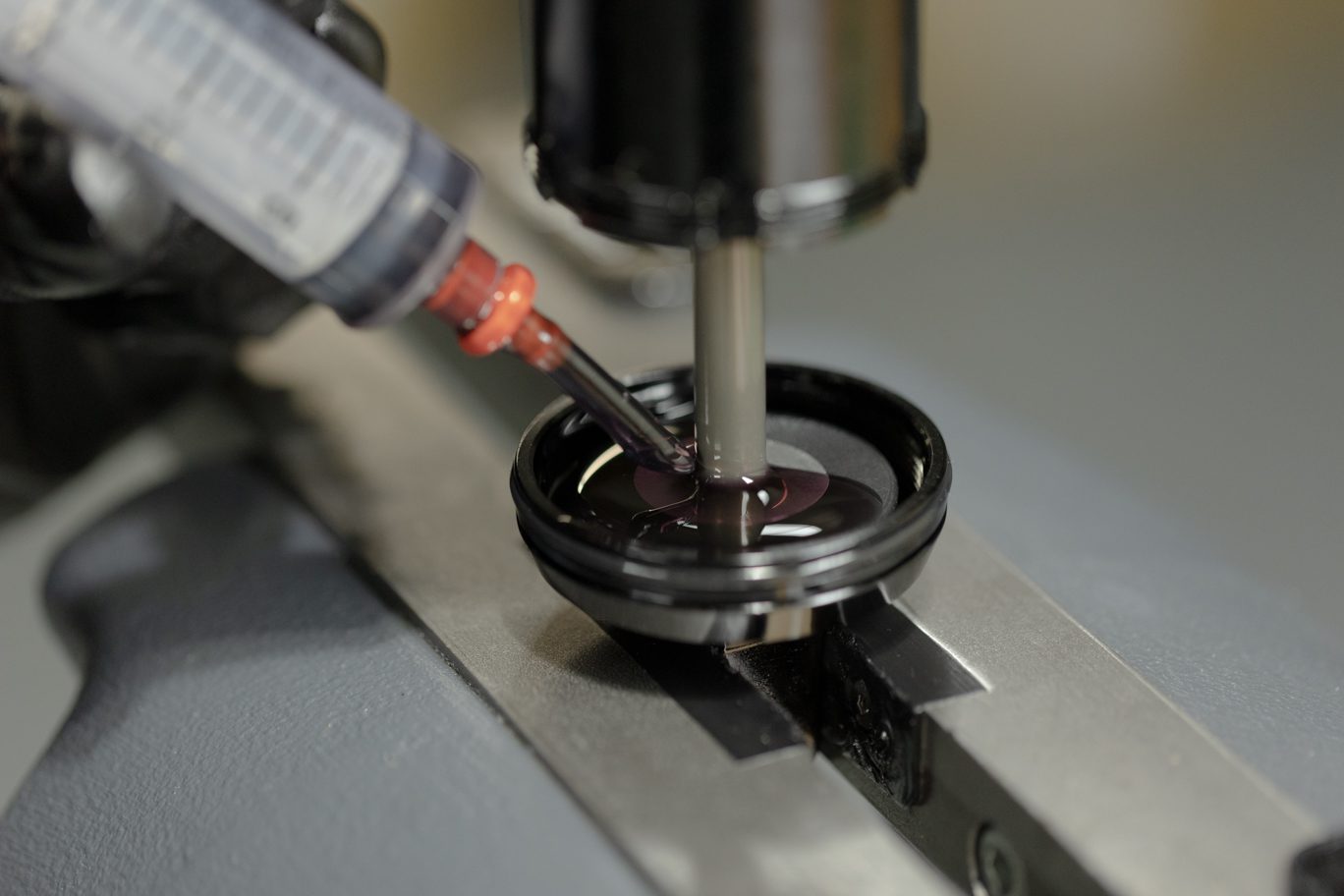
Step 2 – Inner Air Can to End Eye Install
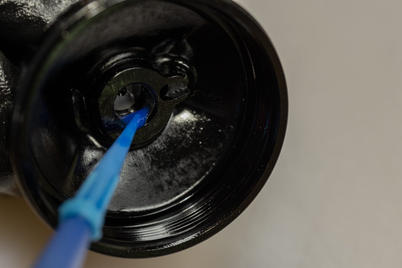
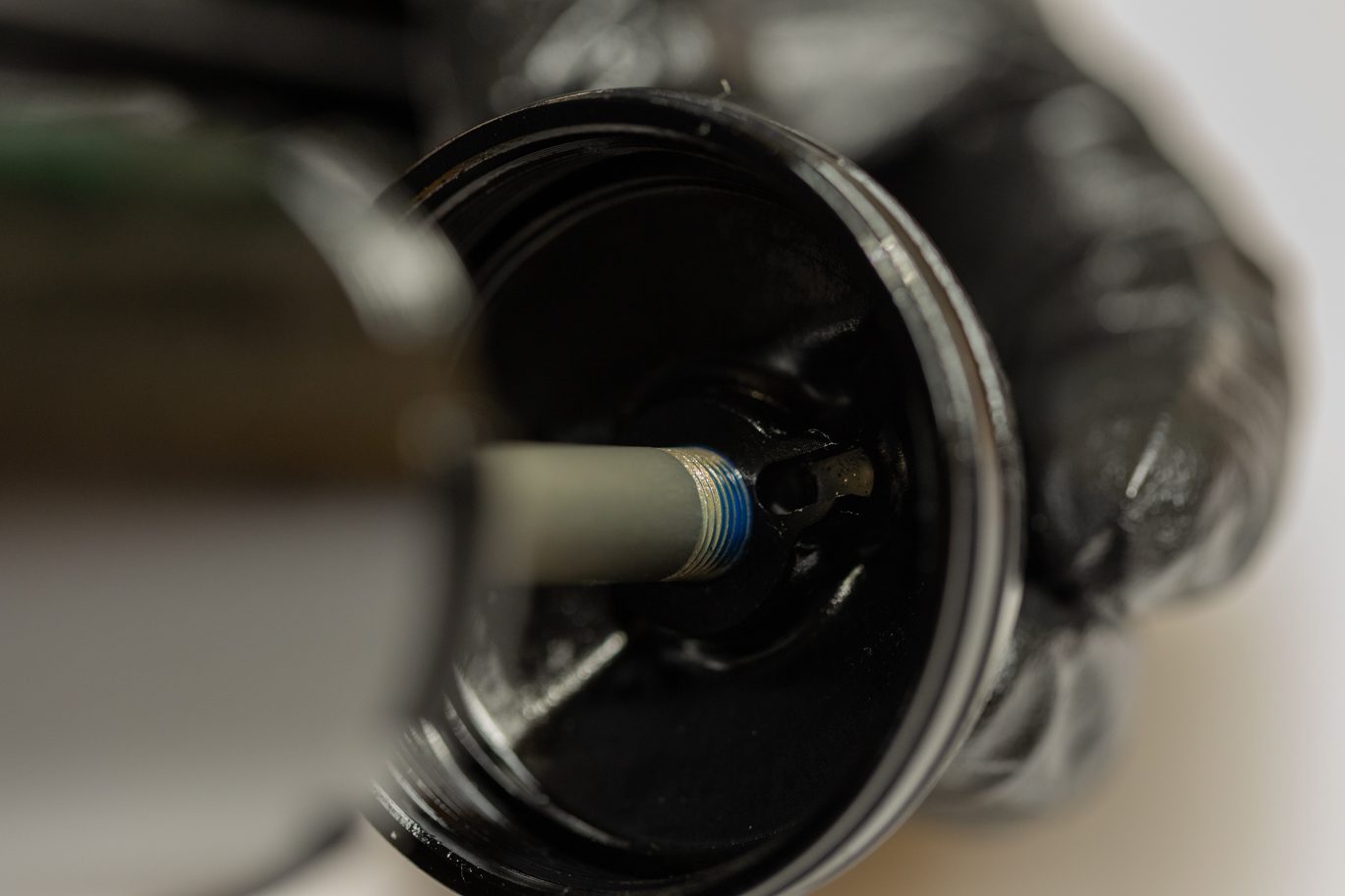
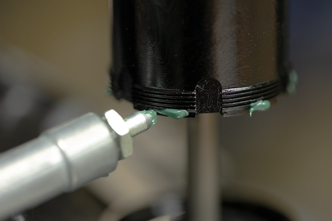
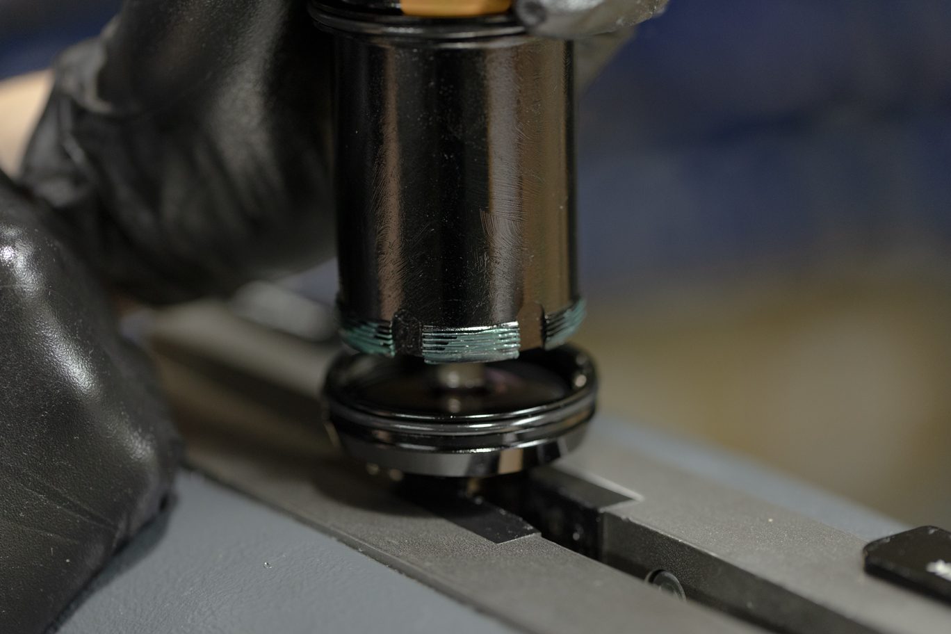
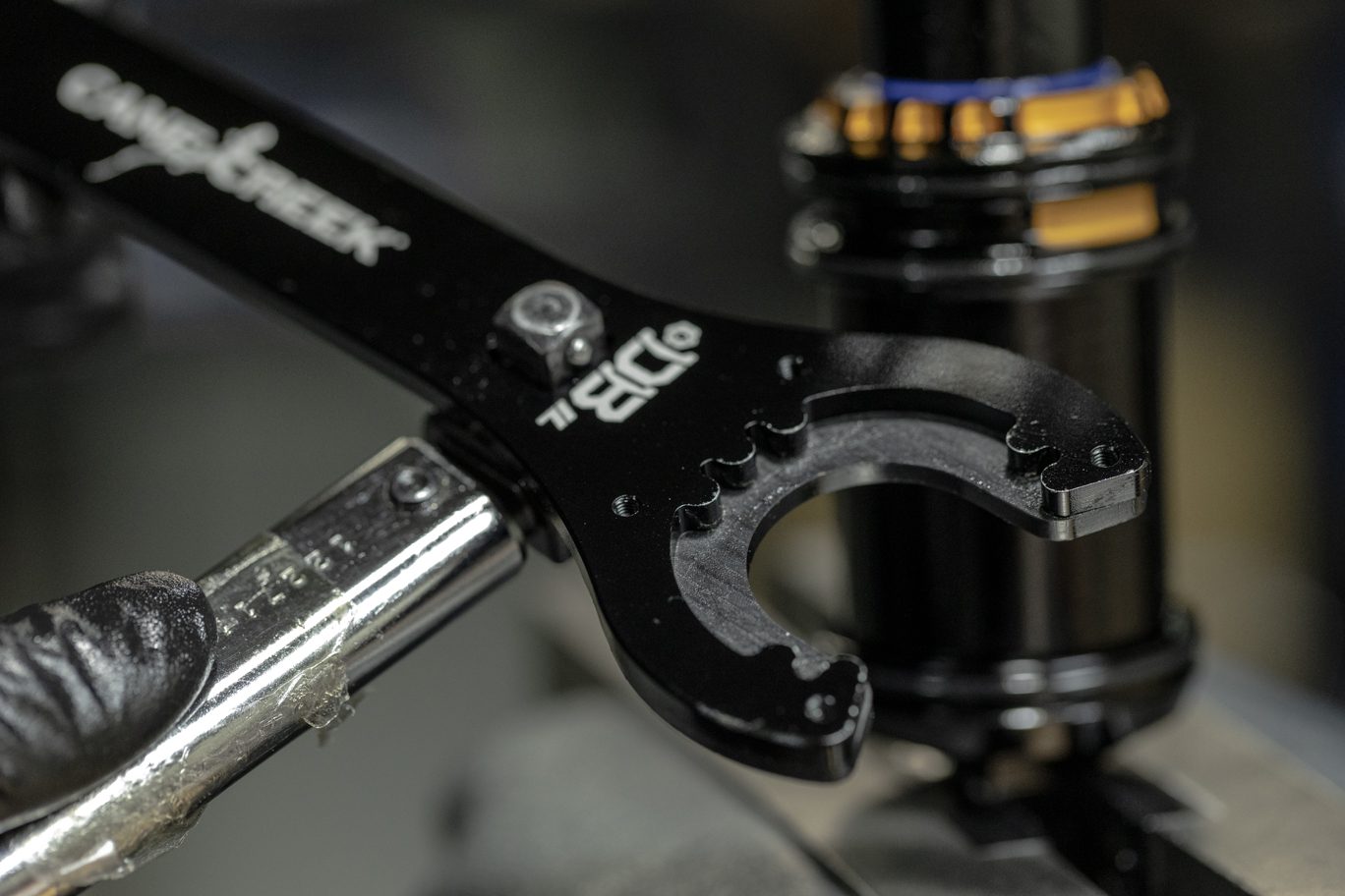
Clamp end eye in vise. Add 5 ml of Royal Purple to end eye. Add PolyLube grease to threads on inner air can. Thread inner air can onto end eye. Torque to 22.6 Nm using Air Seal Head tool.
![](http://b2b.canecreek.com/cdn/shop/files/iLG2-Service-129-of-244.jpg?v=1724872637&width=1920)
Clamped for Inner Air Can to End Eye Install
![](http://b2b.canecreek.com/cdn/shop/files/AIR-IL-TRUNNION-3217.jpg?v=1724872674&width=1368)
Adding Oil to End Eye
![](http://b2b.canecreek.com/cdn/shop/files/AIR-IL-TRUNNION-3222.jpg?v=1724872704&width=1368)
Adding PolyLube to Inner Air Can
![](http://b2b.canecreek.com/cdn/shop/files/AIR-IL-TRUNNION-3223.jpg?v=1724872753&width=1368)
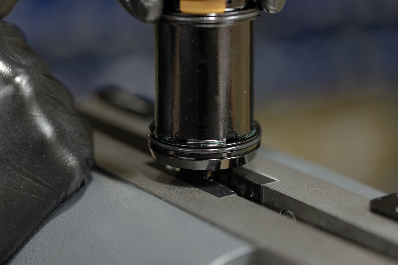
Lowering Inner Air Can onto End Eye
![](http://b2b.canecreek.com/cdn/shop/files/AIR-IL-TRUNNION-3224.jpg?v=1724872797&width=1368)
Threading Inner Air Can onto End Eye
![](http://b2b.canecreek.com/cdn/shop/files/AIR-IL-TRUNNION-3229.jpg?v=1724872841&width=1368)
Air Seal Head Tool
![](http://b2b.canecreek.com/cdn/shop/files/iLG2-Service-132-of-244.jpg?v=1724872920&width=1920)
Using Air Seal Head Tool on Inner Air Can
![](http://b2b.canecreek.com/cdn/shop/files/AIR-IL-TRUNNION-3234.jpg?v=1724873045&width=1368)
![](http://b2b.canecreek.com/cdn/shop/files/AIR-IL-TRUNNION-3235.jpg?v=1724873107&width=1368)
![](http://b2b.canecreek.com/cdn/shop/files/AIR-IL-TRUNNION-3236.jpg?v=1724873139&width=1368)
![](http://b2b.canecreek.com/cdn/shop/files/iLG2-Service-231-of-244.jpg?v=1724873196&width=1920)
![](http://b2b.canecreek.com/cdn/shop/files/iLG2-Service-232-of-244.jpg?v=1724873229&width=1920)
![](http://b2b.canecreek.com/cdn/shop/files/iLG2-Service-233-of-244.jpg?v=1724873266&width=1920)
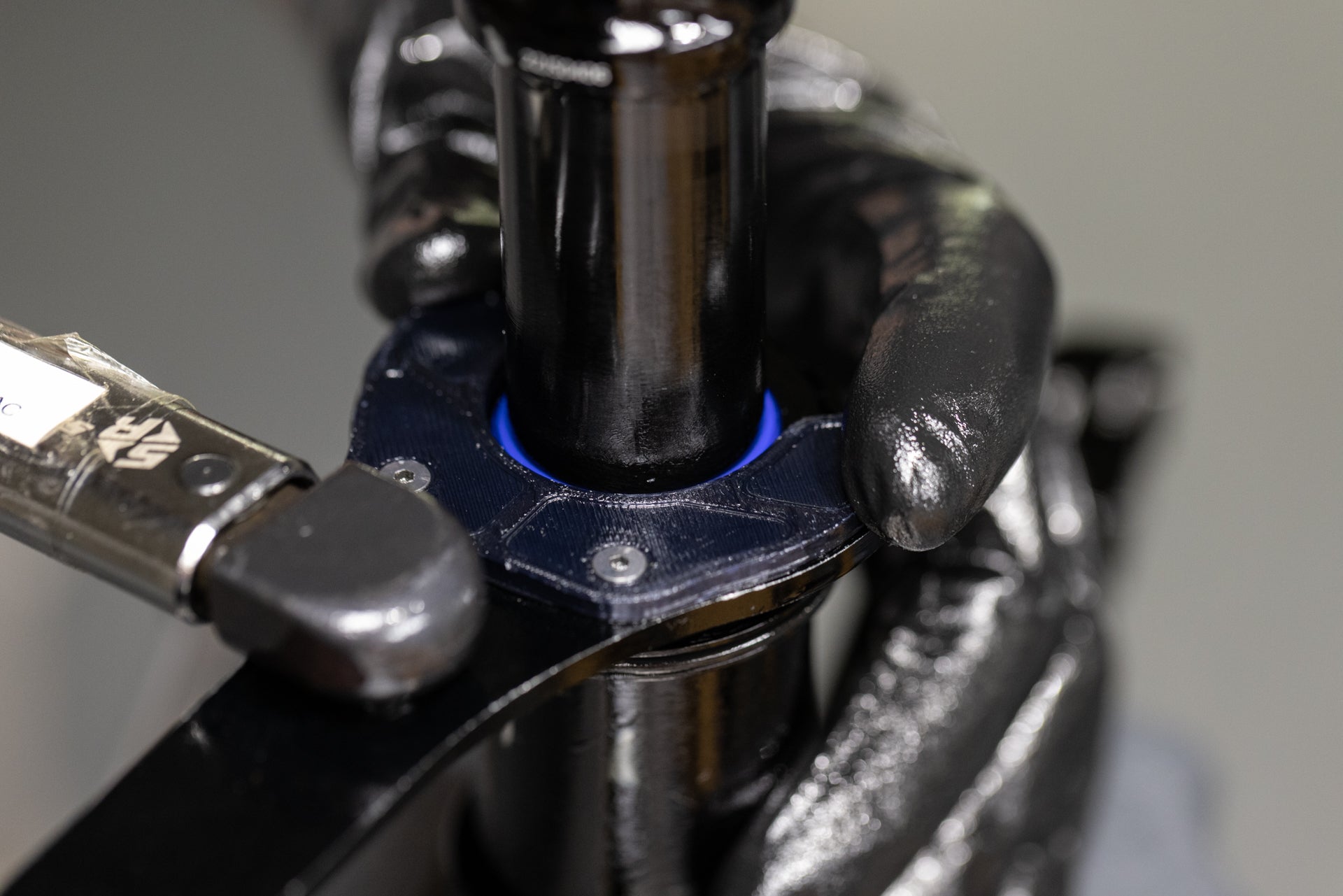
Step 3 – Outer Air Can Install
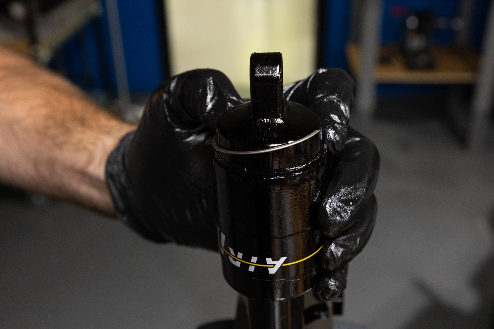
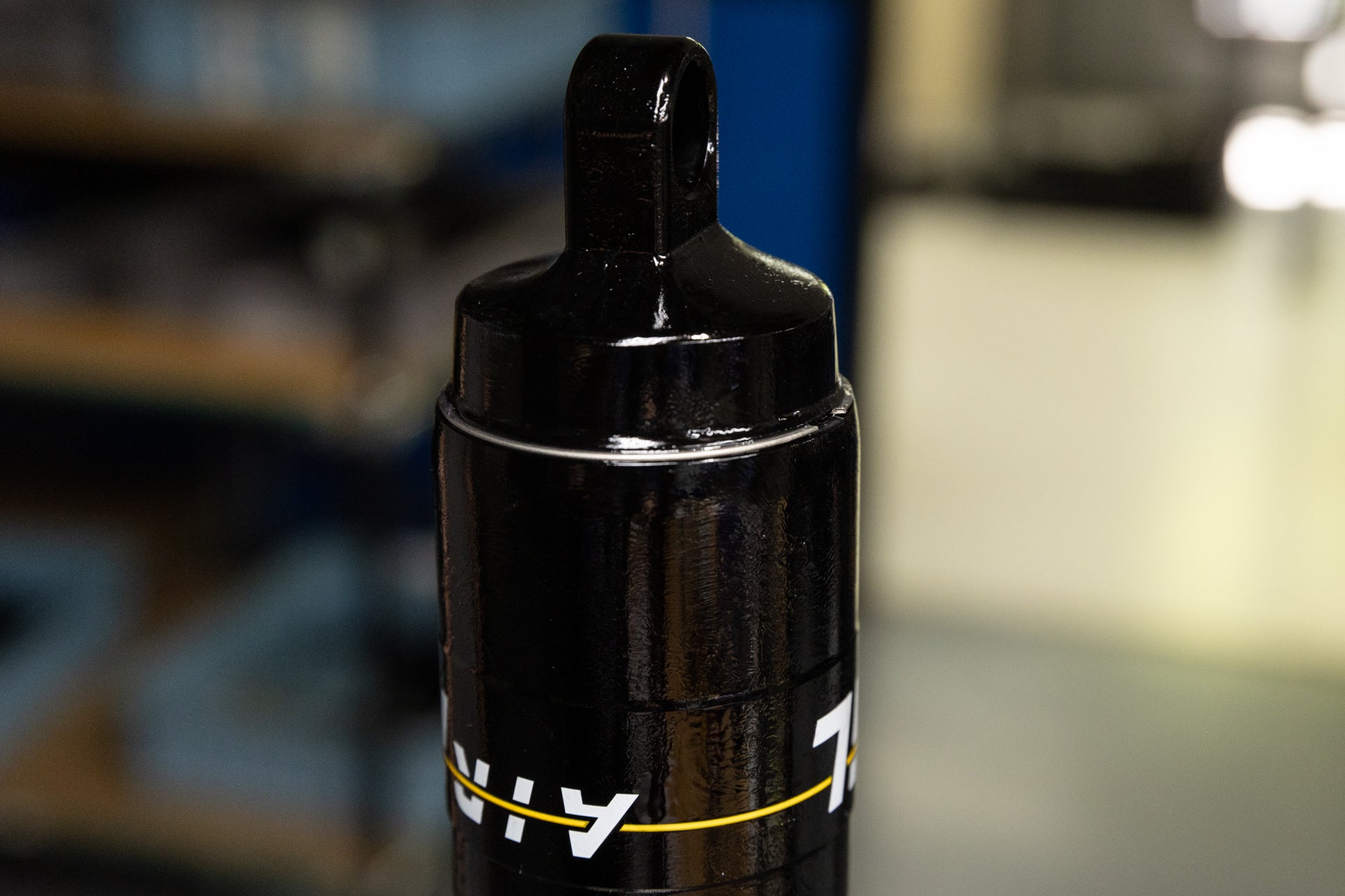
Clamp valve body end into vise. Work outer air can gently past o-rings. Note correct orientation of air can and reinstall any volume reduction. Final o-ring will be tight. Strap wrench may be necessary. Engage Climb Switch to aid installation. Ensure valve is oriented away from Climb Switch. Install outer air can retention clip.
![](http://b2b.canecreek.com/cdn/shop/files/AIR-IL-TRUNNION-3234.jpg?v=1724873045&width=1368)
Shock Clamped (Trunnion)
![](http://b2b.canecreek.com/cdn/shop/files/AIR-IL-TRUNNION-3235.jpg?v=1724873107&width=1368)
Outer Air Can Installation 1
![](http://b2b.canecreek.com/cdn/shop/files/AIR-IL-TRUNNION-3236.jpg?v=1724873139&width=1368)
Outer Air Can Installation 2
![](http://b2b.canecreek.com/cdn/shop/files/iLG2-Service-231-of-244.jpg?v=1724873196&width=1920)
Outer Air Can Installed
![](http://b2b.canecreek.com/cdn/shop/files/iLG2-Service-232-of-244.jpg?v=1724873229&width=1920)
Outer Air Can Retention Clip Install
![](http://b2b.canecreek.com/cdn/shop/files/iLG2-Service-233-of-244.jpg?v=1724873266&width=1920)
Outer Air Can Retention Clip Installed
Final Testing and Set Up
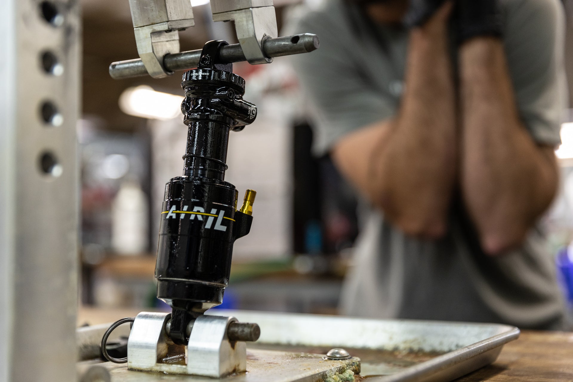
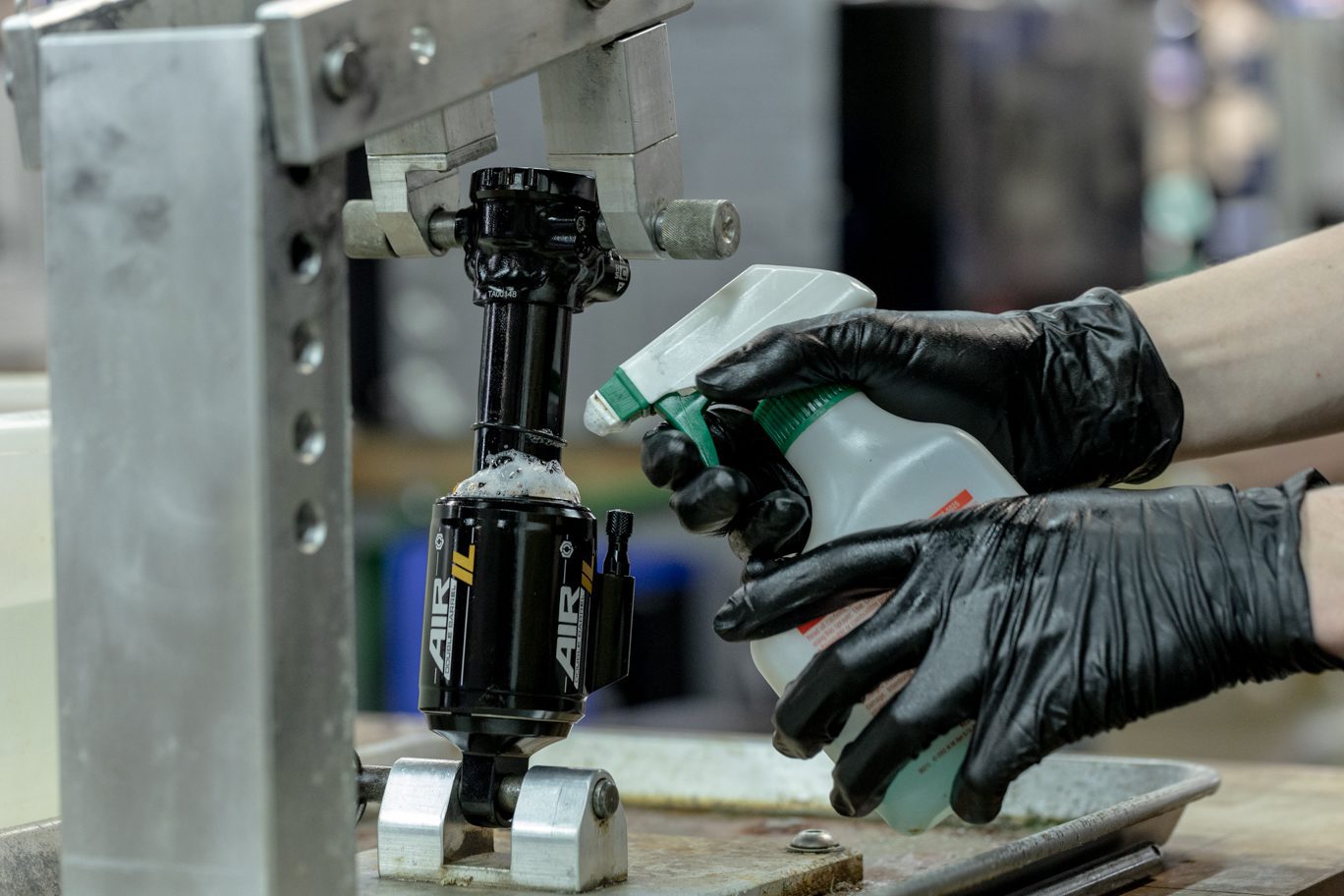
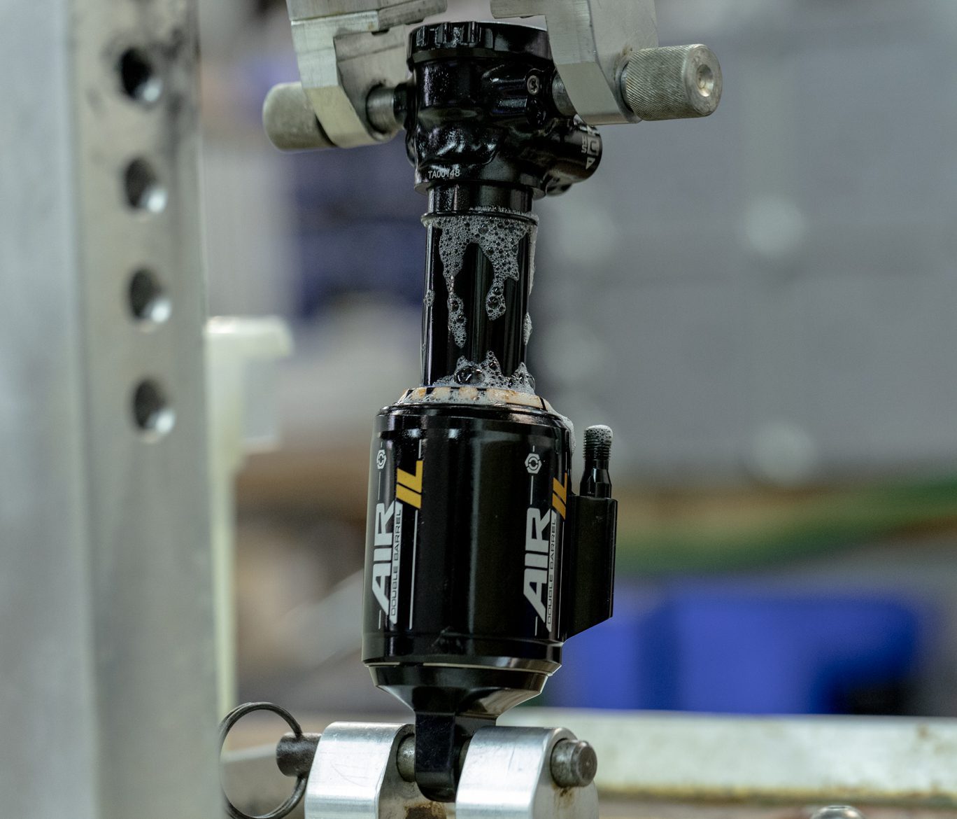
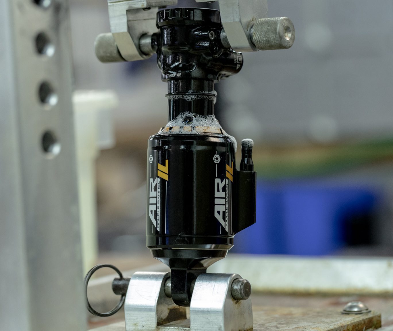
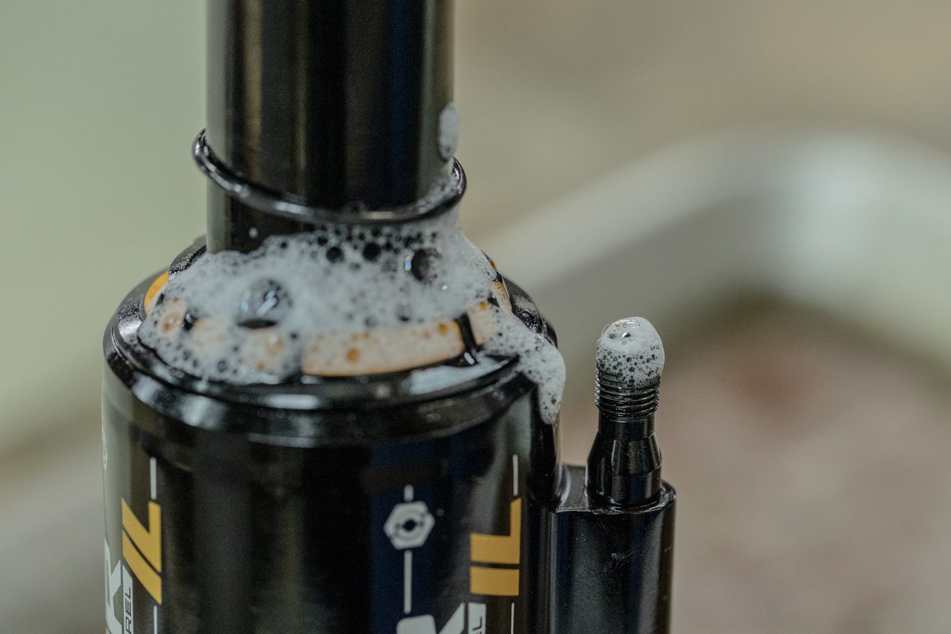
![](http://b2b.canecreek.com/cdn/shop/files/iLG2-Service-234-of-244.jpg?v=1724873352&width=1920)
![](http://b2b.canecreek.com/cdn/shop/files/iLG2-Service-235-of-244.jpg?v=1724873382&width=1920)
![](http://b2b.canecreek.com/cdn/shop/files/AIR-IL-TRUNNION-3246.jpg?v=1724873412&width=1368)
![](http://b2b.canecreek.com/cdn/shop/files/AIR-IL-TRUNNION-3254.jpg?v=1724873442&width=1368)
![](http://b2b.canecreek.com/cdn/shop/files/AIR-IL-TRUNNION-3253.jpg?v=1724873466&width=1368)
![](http://b2b.canecreek.com/cdn/shop/files/AIR-IL-TRUNNION-3249.jpg?v=1724873490&width=1368)
![](http://b2b.canecreek.com/cdn/shop/files/iLG2-Service-236-of-244.jpg?v=1724873512&width=1920)
Step 1 – Leak Check
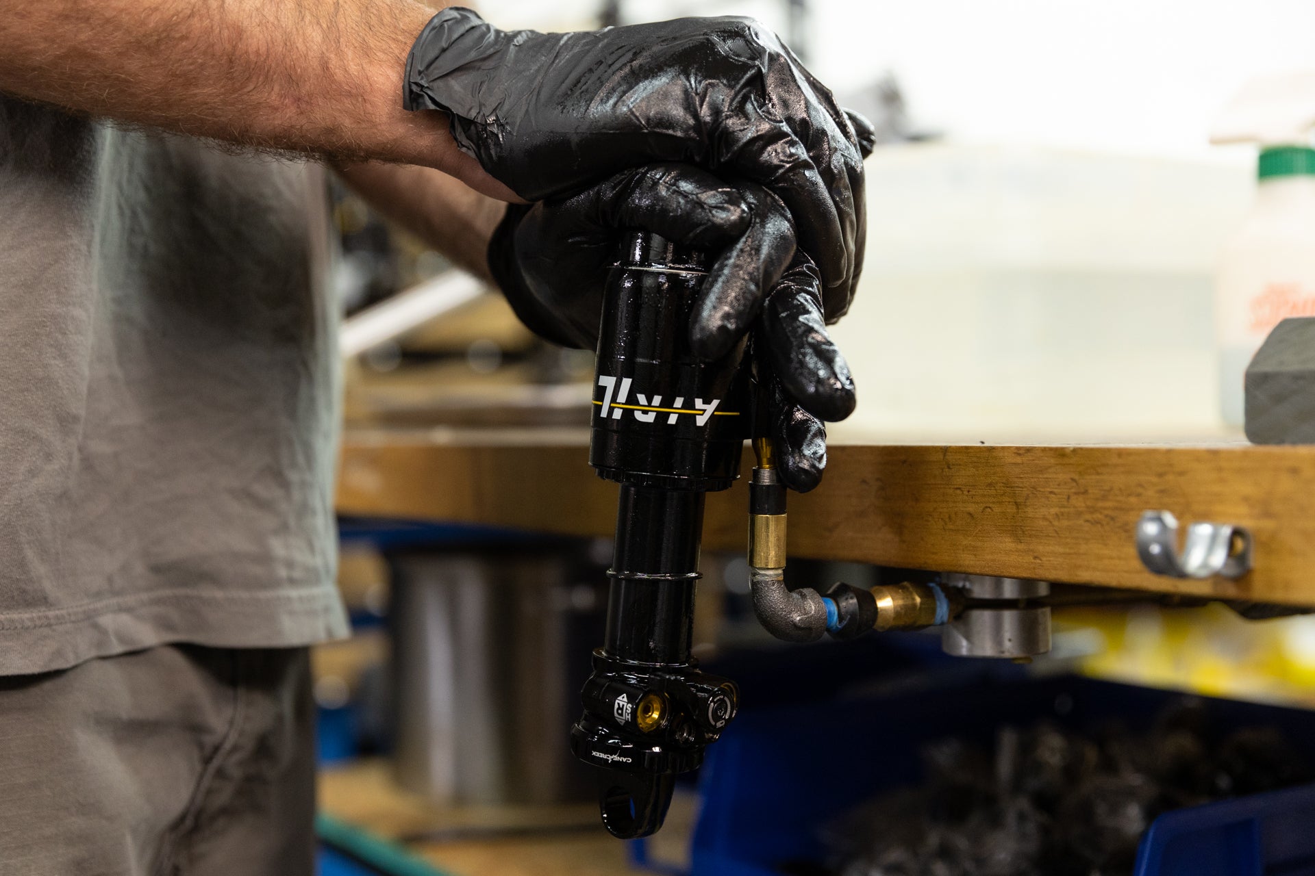
Air up shock to at least 100 psi. On hand dyno or bike frame, slowly cycle shock and listen for negative volume chamber to pressurize. Using soapy water and dunk tank, test for any possible air leaks. Install valve cap.
![](http://b2b.canecreek.com/cdn/shop/files/iLG2-Service-234-of-244.jpg?v=1724873352&width=1920)
Airing Up Shock
![](http://b2b.canecreek.com/cdn/shop/files/iLG2-Service-235-of-244.jpg?v=1724873382&width=1920)
Shock on Hand Dyno
![](http://b2b.canecreek.com/cdn/shop/files/AIR-IL-TRUNNION-3246.jpg?v=1724873412&width=1368)
Soap Test 1
![](http://b2b.canecreek.com/cdn/shop/files/AIR-IL-TRUNNION-3254.jpg?v=1724873442&width=1368)
Soap Test 2
![](http://b2b.canecreek.com/cdn/shop/files/AIR-IL-TRUNNION-3253.jpg?v=1724873466&width=1368)
Soap Test 3
![](http://b2b.canecreek.com/cdn/shop/files/AIR-IL-TRUNNION-3249.jpg?v=1724873490&width=1368)
Soap Test 4
![](http://b2b.canecreek.com/cdn/shop/files/iLG2-Service-236-of-244.jpg?v=1724873512&width=1920)
Dunk Test
![](http://b2b.canecreek.com/cdn/shop/files/AIR-IL-TRUNNION-3260.jpg?v=1724873597&width=1368)
![](http://b2b.canecreek.com/cdn/shop/files/AIR-IL-TRUNNION-3261.jpg?v=1724873632&width=1368)
![](http://b2b.canecreek.com/cdn/shop/files/iLG2-Service-183-of-244_39406e00-b9e2-41b1-b01c-a482d15ae307.jpg?v=1724873758&width=1920)
Step 2 – Dyno Test
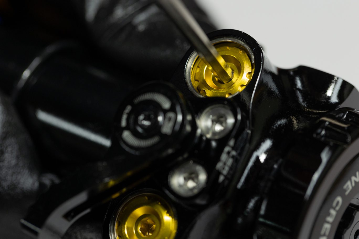
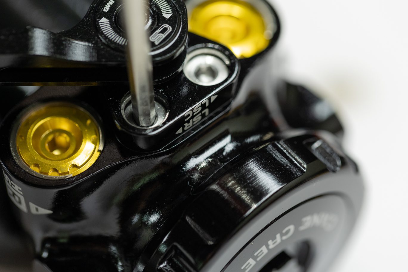
Set adjusters to factory neutral: HSC & HSR 2.5 turns from full bottom (or 2 turns from full open); LSC 11 clicks from full bottom; LSR 13 from full bottom. Using hand dyno, test shock for function. Ensure Climb Switch engages and operates properly. Turn individual adjusters to test each one. Set back to original tune if desired.
Install any bushings and hardware.
![](http://b2b.canecreek.com/cdn/shop/files/AIR-IL-TRUNNION-3260.jpg?v=1724873597&width=1368)
High Speed Adjust
![](http://b2b.canecreek.com/cdn/shop/files/AIR-IL-TRUNNION-3261.jpg?v=1724873632&width=1368)
Low Speed Adjust
![](http://b2b.canecreek.com/cdn/shop/files/iLG2-Service-183-of-244_39406e00-b9e2-41b1-b01c-a482d15ae307.jpg?v=1724873758&width=1920)